
Teach Yourself Basic Games Programming (1984)
- Pages
- 71
- Source
- scanned, Teach_Yourself_Basic_Games_Programming_1984_NZ.pdf
- Per page
- about 85 KB — only what you read
- Text layer
- yes — searchable

Basic Games Programming
Chapter One
SPRITES AND GRAPHICS
How to work in binary, hexidecimal and decimals
Designing Sprites and Graphics
Use of Colour in programs.
Chapter Two
SOUND
Beep Command
Sound Command
Sound Effects and Music
Chapter Three
SOUND
How to use the keyboard in games
Use of joystics
Chapter Four
GAMES PROGRAMMING AS AN ART
Manipulating the screen
Video Ram Map
Use of VPOKE and VPEEK
Run Down of “Maze-Chase”
GLOSSARY
2
Introduction
The Sega SC3000 has been with us a short while now, and some ex-
cellent programs are emerging sporting excellent graphics and sound,
Dollar for dollar the SC3000 beats most home micro’s as far as graphic
and sound capabilities are concerned. The reason for this is that Sega
have been in the Video Game industry a long time and have many years
of experience behind them in dealing with such matters.
This book and program will show you how to develop programming
skills in games writing by producing stunning graphics and sound. The
book and program are meant to run hand-in-hand, therefore,
it is im-
portant that you always cross reference.
The book contains numerous exercises and programs for you to ex-
periment with.
One final note, when experimenting with graphics and sound remember
to always say to yourself “What would happen if
?”, try alter-
ing a few variables, add a few lines, delete a few lines, you may amaze
yourself with what results you get!
ENJOY YOURSELF
3
CHAPTER ONE
Sprites and Graphics
HOW TO WORK IN BINARY, HEXADECIMAL AND DECIMAL
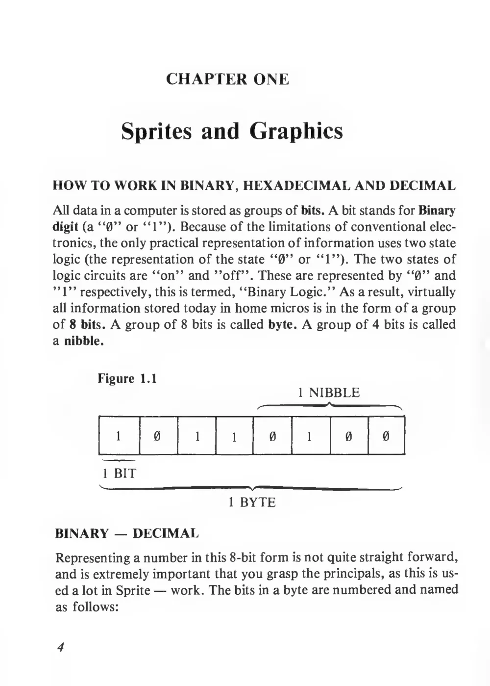
All data in a computer is stored as groups of bits. A bit stands for Binary
digit (a “0” or “1”). Because of the limitations of conventional elec-
tronics, the only practical representation of information uses two state
logic (the representation of the state “0” or “1”). The two states of
logic circuits are “on” and ’’off”. These are represented by “0” and
”1” respectively, this is termed, “Binary Logic.” As a result, virtually
all information stored today in home micros is in the form of a group
of 8 bits. A group of 8 bits
is called byte. A group of 4 bits is called
a nibble.
Figure
1.1
1 NIBBLE
1
0
1
1
0
1
0
0
1 BIT
-
v —
1
1 BYTE
BINARY — DECIMAL
Representing a number in this 8-bit form is not quite straight forward,
and is extremely important that you grasp the principals, as this is us-
ed a lot in Sprite — work. The bits in a byte are numbered and named
as follows:
4
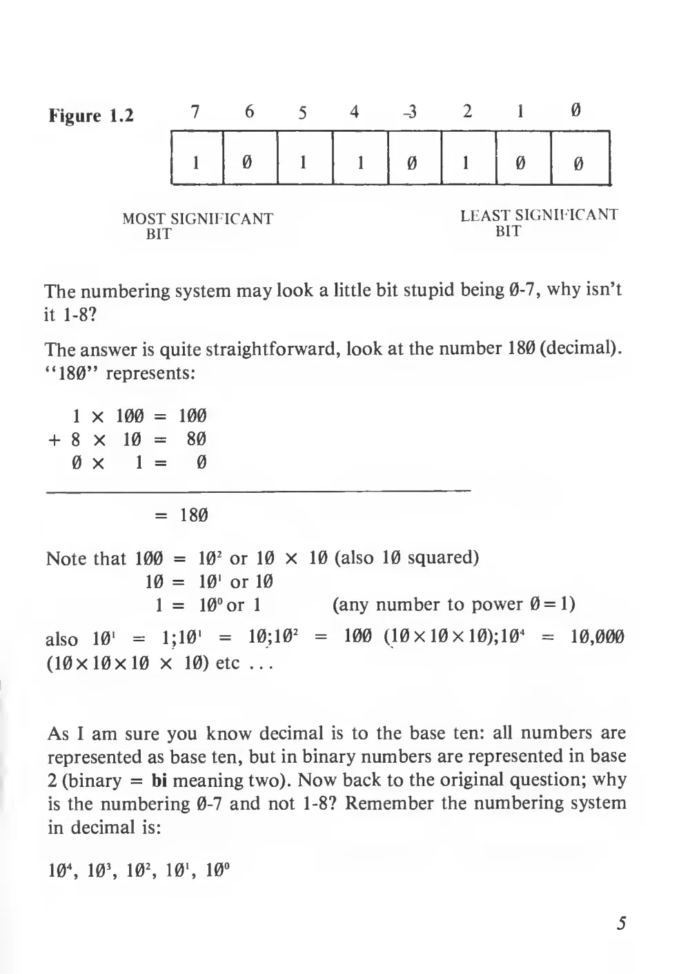
Figure 1.2
7
6
5
4
-3
2
1
0
1
0
1
1
0
1
0
0
MOST SIGNIFICANT
LEAST SIGNIFICANT
BIT
BIT
The numbering system may look a little bit stupid being 0-7, why isn’t
it 1-8?
The answer is quite straightforward, look at the number 180 (decimal).
“180” represents:
1 x
100 =
100
+
8
x
10 =
80
0 x
1 =
0
=
180
Note that 100 =
10
2 or 10 X
10 (also 10 squared)
10 =
10' or 10
1 =
10° or
1
(any number to power 0=1)
also
10
1
=
1
; 1
0
1
=
10; 10
2
=
100
(10 X 10 x 10);10
4
=
10,000
(10X 10x 10 x
10) etc
...
As
I am sure you know decimal
is to the base ten:
all numbers are
represented as base ten, but in binary numbers are represented in base
2 (binary =
bi meaning two). Now back to the original question; why
is the numbering 0-7 and not 1-8? Remember the numbering system
in decimal
is:
10\
10\
10
2
,
10 ',
10
°
5
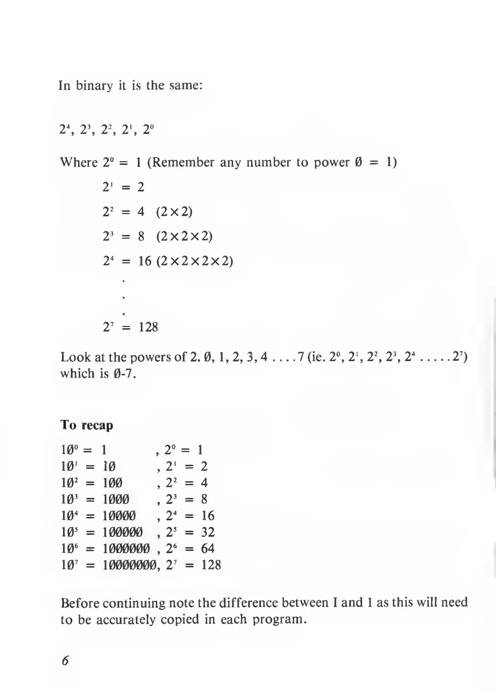
In binary
it
is the same:
2\ 2\ 2
2
, 2 ', 2
°
Where 2° =
1 (Remember any number to power 0=1)
2
' =
2
2
2 = 4
(2x2)
2
3 =
8
(2X2X2)
2
4 =
16 (2x2x2x2)
2
7 =
128
Look at the powers of 2. 0,
1, 2, 3, 4 ... .7 (ie. 2°, 2 \ 2
2
, 2\ 2
4
2
7
)
which
is 0-7.
To recap
10 ° =
1
, 2 ° =
10
1 =
10
, 2
‘ =
10
2 =
100
, 2
2 =
10
3 =
1000
, 2
3 =
10
4 =
10000
, 2
4 =
10
5 =
100000
, 2
5 =
10
6 =
1000000
, 2
6 =
10
7 =
10000000 , 2
7 =
1
2
4
8
16
32
64
128
Before continuing note the difference between
I and
1 as this will need
to be accurately copied in each program.
6
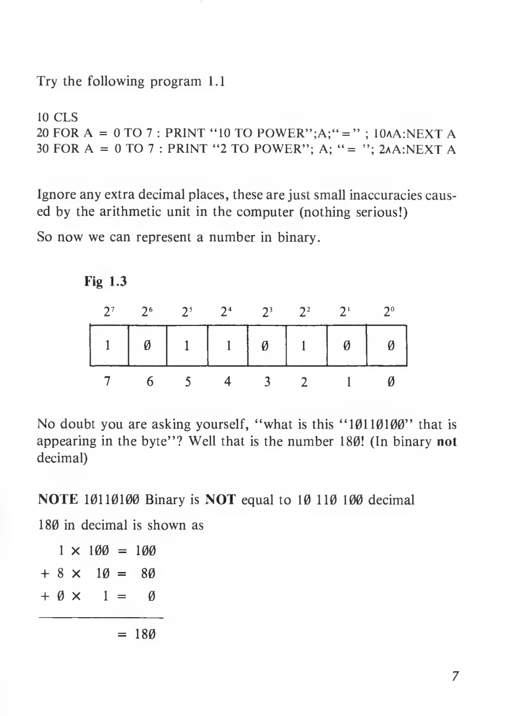
Try the following program
1.1
10 CLS
20 FOR A = 0 TO 7
: PRINT “10 TO POWER”;A;“ = ”
; 10AA:NEXT A
30 FOR A = 0 TO 7
: PRINT “2 TO POWER”; A; “=
2aA:NEXT A
Ignore any extra decimal places, these are just small inaccuracies caus-
ed by the arithmetic unit in the computer (nothing serious!)
So now we can represent a number in binary.
Fig
1.3
2
7
2
6
2
5
2
4
2
3
2
2
2'
2°
1
0
1
1
0
1
0
0
7
6
5
4
3
2
1
0
No doubt you are asking yourself, “what
is this “10110100” that
is
appearing in the byte”? Well that
is the number
180!
(In binary not
decimal)
NOTE 10110100 Binary
is NOT equal to
10 110 100 decimal
180 in decimal
is shown as
1 x
100 =
100
+ 8x
10 =
80
+ 0 x
1
=
0
=
180
7
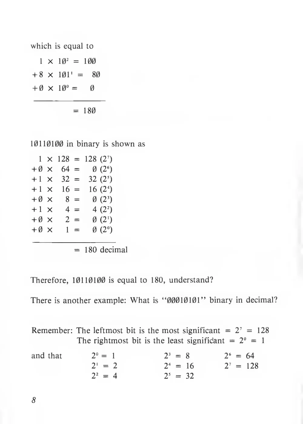
which
is equal to
1
X
10
2 =
100
+ 8 X
101' =
80
+ 0 X
10° =
0
=
180
10110100 in binary
is shown as
1
X
128 =
128 (2
7
)
+ 0 X
64 =
0 (2
6
)
+
1
X
32 =
32 (2
5
)
+
1
X
16 =
16 (2
4
)
+ 0 X
8 =
0 (2
3
)
+
1 X
4 =
4 (2
2
)
+0 X
2 =
0 (2')
+ 0 X
1 =
0 (2°)
=
180 decimal
Therefore, 10110100
is equal to
180, understand?
There
is another example: What
is “00010101” binary in decimal?
Remember: The leftmost
bit
is the most significant =
2
7 =
The rightmost bit
is the least significant =
2° =
and that
2
3 =
8
2
4 =
16
2
5 =
32
128
1
8
2 ° =
1
2
' =
2
2
2 =
4
2
6 = 64
2
7 =
128
Therefore 00010101
0 X
128 =
0
+0 X
64 =
0
+0 X
32 =
0
+
1
X
16 =
16
+0 X
8 = 0
+
1
X
4 = 4
+0 X
2 =
0
+
1
X
1 =
1
=
21 decimal
The following program allows you to enter an 8-digit binary number
and the decimal version
is produced.
Program 1.2
10 INPUT“ENTER A BINARY # (LENGTH = 8)”;B$
20 IF LEN (B$)< >8 THEN
10
30 DATA
128, 64, 32,
16,
8, 4,
2,
1
40 RESTORE: T = 0:FOR A =
1 TO
8: READ
B:
IFMID$(B$,A,1) = “
1 ’’THEN
T = T + B
50 NEXT A
60 PRINT “DECIMAL = ”;T
LINE 10
The command input tells the computer to expect infor-
mation from
the keyboard operator,
this information
must be numeric,
ie. 0 and
1. Whatever
is inserted in
quotation marks after the command will be displayed on
screen as a prompt, the information
is then stored in a
memory location which is labeled by you, in this instance
we have chosen B$.
9
LINE 20
LINE 30
LINE 40
LINE 50
Checks the length to make sure if the information is the
required length ie. if the length of the information stored
in location B$
is less than, 8, or greater than 8 then go
back to line 10 and ask for the information again. If not
then go on to the next part of the program.
Holds the data to be read and used by the program in
sequence.
(see page 63-64 handbook). Restore. Tells the computer
if
it has read a full line of data previously, that
it can
go back and read a data line again from the beginning.
T = 0 sets the value of variable T, to 0. For A =
1 to 8
sets the value of A to firstly
1, then 2 and so on up to
8. Read B sends the program to the data line, where
it
reads the first piece of information (128) and loads it in-
to the location called B. Next the program says the com-
puter must look at aspecific part of the information stored
as B$ which would have been entered as a mixture of 8
zero’s and ones. This is done by using Mid B$ (see page
83) where you must tell the computer where it must start
looking in the length of the string and where it must stop.
In this case
it starts looking at A and as A =
1 to
8, A
is first of all,
1, then it finishes looking there as the next
number is also a
1 which means it only wants one number,
therefore, IF the section we are looking for in B$ which
is the first number of the 8 that are there = “1” then
the number stored in T which was 0 is now to be added
to whatever
is stored in B, which
is at the moment 128
if not leave T as
it
is.
Next A sends the program back to the part of the pro-
gram where A was established, and as A was originally
10
1,
it now becomes 2, and then continues along the line,
reading B, having already read the
1st piece of data
it
goes to the next and replaces that new value in location
B. (64)
It now looks again at the list of numbers in B$
and as A now
is 2, looks at the second digit in the row
to see
if that
is a 0 or a
1,
if
it
is a
1 then the number
in B
is added to the number in T. If
it
is a 0, T stays as
it is. This will continue until A reaches 8, when there are
no more values left to be given to A,
it continues to the
next line.
LINE 60
The computer displays whatever
is between quotation
marks on screen, and displays whatever the ultimate
value
is stored at T.
NOTE:
It is very important that you get into the habit of showing all
preceding “0”
’s in binary (eg. 00010101
not 10101).
EXERCISES
1.1 How many bites are there in a nibble?
1.2 How many nibbles in a byte?
1.3 What two digits are used in binary?
1.4 What
is “11111111”
in decimal?
1.5 What
is “00000000”
in decimal?
1.6 From
the
above two
questions
what
are
the minimum
and
maximum number that an 8 bit byte can represent?
ANSWERS ON PAGE 36
Decimal — Binary
Now that you know how to convert Binary to Decimal,
lets see how
decimal is changed to binary.
11
This
is very simple indeed, as an example take the decimal number 49
to binary.
49 -r 2
=
24,
1
remainder
1
—
1
^24 + 2
=
12,
remainder
0
—
0
^12 h- 2
=
6,
1
remainder
0
—
0
^ 6 -h 2
=
3,
i
remainder
0
—
0
^
3 h- 2
=
1,
1
remainder
1
—
1
^
1
-r 2
—
0,
remainder
1
—
1
The binary equivalent is
1 10001 (read right-most column from bottom
to top), but remember
1 10001 is not correct as it contains only 6 digits,
therefore, pad out with “0”
’s — 00110001:
therefore 49 decimal = 00110001 binary. Easy!
The following program converts decimal binary.
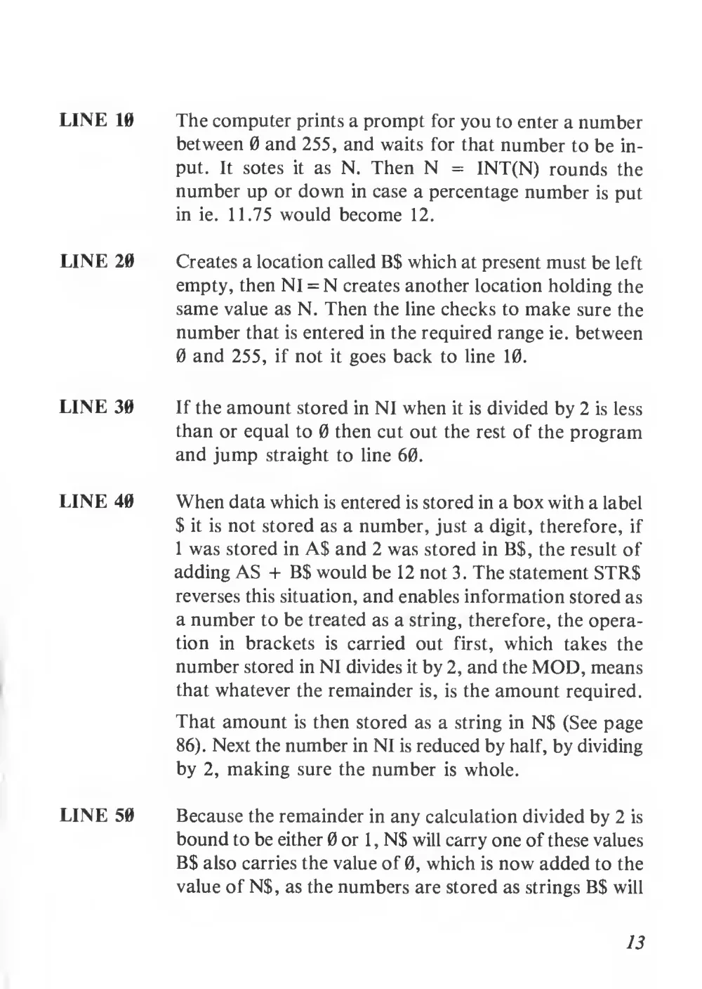
PROGRAM 1.3
10 INPUT“ENTER A NUMBER (0-255):”;N:N = INT (N)
20 B$ = “”:N1 =N:IF N <0 OR N >255 THEN 10
30 IF Nl/2< =0 THEN 60
40 N$ = STR$(N1 MOD 2):N1 = INT(Nl/2)
50 N$ = RIGHT$(N$,1):B$ = N$ + B$:GOTO 30
60 IF LEN (B$)< >8THENB$ = “0” + B$:GOTO 60
70 CLSiPRINT N;“ = ”;B$
12
LINE 10
LINE 20
LINE 30
LINE 40
LINE 50
The computer prints a prompt for you to enter a number
between 0 and 255, and waits for that number to be in-
put.
It
sotes
it
as N. Then N =
INT(N) rounds the
number up or down in case a percentage number
is put
in
ie.
11.75 would become
12.
Creates a location called B$ which at present must be left
empty, then NI = N creates another location holding the
same value as N. Then the line checks to make sure the
number that is entered in the required range ie. between
0 and 255,
if not
it goes back to line
10.
If the amount stored in NI when it is divided by 2 is less
than or equal to 0 then cut out the rest of the program
and jump straight to line 60.
When data which is entered is stored in a box with a label
$
it
is not stored as a number, just a digit, therefore,
if
1 was stored in A$ and 2 was stored in B$, the result of
adding AS + B$ would be 12 not 3. The statement STR$
reverses this situation, and enables information stored as
a number to be treated as a string, therefore, the opera-
tion
in
brackets
is
carried
out
first, which
takes
the
number stored in NI divides it by 2, and the MOD, means
that whatever the remainder
is,
is the amount required.
That amount
is then stored as a string in N$ (See page
86). Next the number in NI is reduced by half, by dividing
by 2, making sure the number
is whole.
Because the remainder in any calculation divided by 2 is
bound to be either 0 or
1
, N$ will carry one of these values
B$ also carries the value of 0, which is now added to the
value of N$, as the numbers are stored as strings B$ will
13
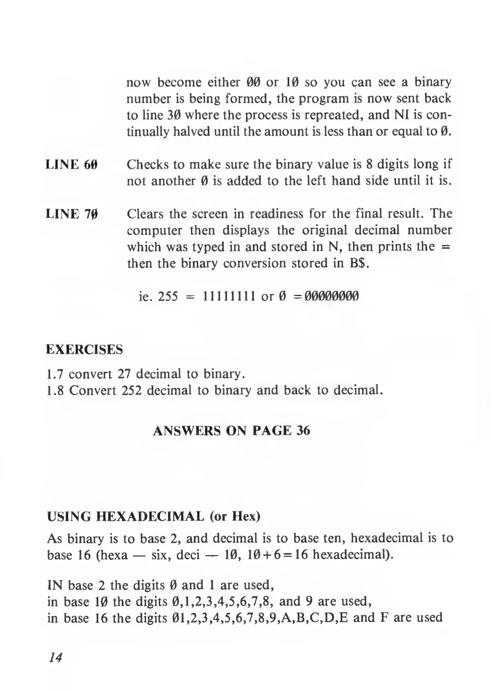
now become either 00 or
10 so you can see a binary
number is being formed, the program
is now sent back
to line 30 where the process is repreated, and NI is con-
tinually halved until the amount is less than or equal to 0.
LINE 60
Checks to make sure the binary value
is 8 digits long if
not another 0
is added to the
left hand side until
it
is.
LINE 70
Clears the screen in readiness for the final result. The
computer
then
displays
the
original
decimal number
which was typed in and stored in N, then prints the =
then the binary conversion stored
in B$.
ie. 255 =
11111111 or 0 =00000000
EXERCISES
1.7 convert 27 decimal to binary.
1.8 Convert 252 decimal to binary and back to decimal.
ANSWERS ON PAGE 36
USING HEXADECIMAL (or Hex)
As binary
is to base 2, and decimal
is to base ten, hexadecimal
is to
base 16 (hexa — six, deci —
10,
10 + 6 = 16 hexadecimal).
IN base 2 the digits 0 and
1 are used,
in base 10 the digits 0,1, 2, 3, 4, 5, 6, 7, 8, and 9 are used,
in base 16 the digits 01,2,3,4,5,6,7,8,9,A,B,C,D,E and F are used
14
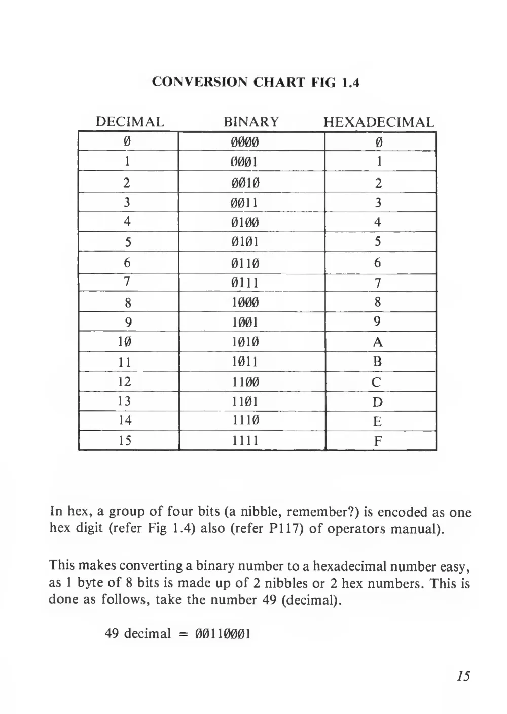
CONVERSION CHART FIG
1.4
DECIMAL
BINARY
HEXADECIMAL
0
0000
0
1
0001
l
2
0010
2
3
0011
3
4
0100
4
5
0101
5
6
0110
6
7
0111
7
8
1000
8
9
1001
9
10
1010
A
11
101
B
12
1100
C
13
1101
D
14
1110
E
15
mi
F
In hex, a group of four bits (a nibble, remember?)
is encoded as one
hex digit (refer Fig
1.4) also (refer PI 17) of operators manual).
This makes converting a binary number to a hexadecimal number easy,
as
1 byte of 8 bits
is made up of 2 nibbles or 2 hex numbers. This
is
done as follows, take the number 49 (decimal).
49 decimal = 00110001
15
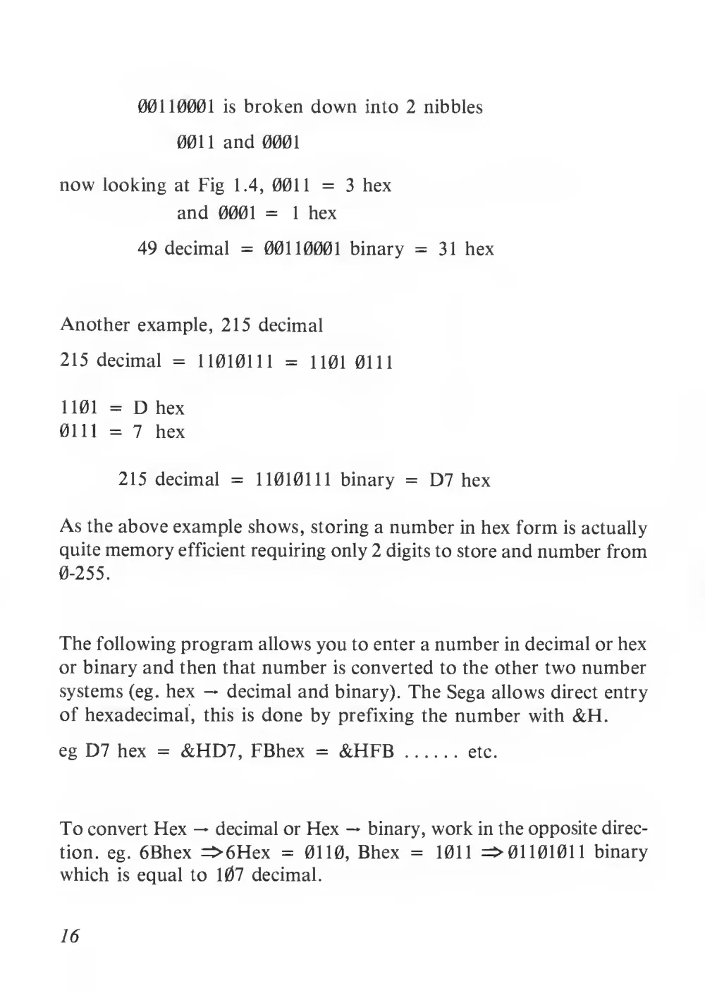
00110001
is broken down into 2 nibbles
0011 and 0001
now looking at Fig
1.4, 0011
=
3 hex
and 0001 =
1 hex
49 decimal = 00110001 binary =
31 hex
Another example, 215 decimal
215 decimal =
11010111 =
1101 0111
1101 = D hex
0111 =
7
hex
215 decimal =
11010111 binary = D7 hex
As the above example shows, storing a number in hex form is actually
quite memory efficient requiring only 2 digits to store and number from
0-255.
The following program allows you to enter a number in decimal or hex
or binary and then that number is converted to the other two number
systems (eg. hex — decimal and binary). The Sega allows direct entry
of hexadecimal,
this
is done by prefixing the number with &H.
eg D7 hex = &HD7, FBhex = &HFB
etc.
To convert Hex — decimal or Hex — binary, work in the opposite direc-
tion.
eg. 6Bhex =>6Hex =
0110, Bhex =
1011 =>01101011 binary
which
is equal to 107 decimal.
16
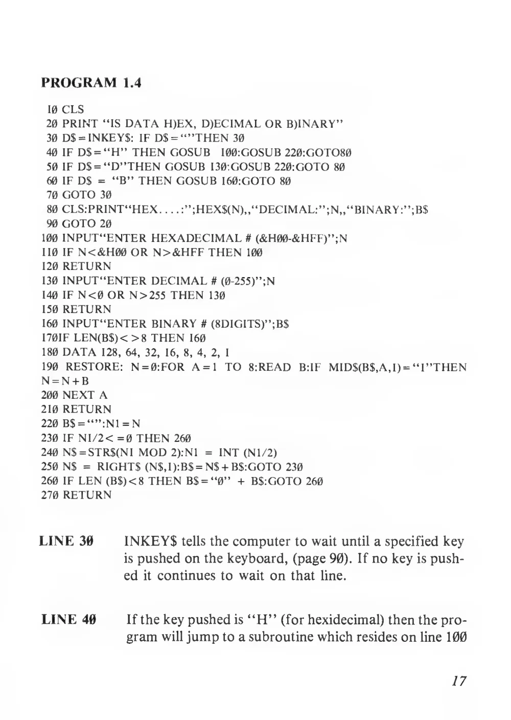
PROGRAM
1.4
10 CLS
20 PRINT “IS DATA H)EX, D)ECIMAL OR B)INARY”
30 D$ = INKEYS: IF D$ = “”THEN 30
40 IF D$ = “H” THEN GOSUB
100:GOSUB 220:GOTO80
50 IF D$ = “D’’THEN GOSUB 130:GOSUB 220:GOTO 80
60 IF D$ = “B” THEN GOSUB 160:GOTO 80
70 GOTO 30
80 CLS:PRINT“HEX.
.
.
. :”;HEX$(N),,“DEC1MAL:”;N„“BINARY:”;B$
90 GOTO 20
100 INPUT“ENTER HEXADECIMAL # (&H00-&HFF)”;N
110 IF N<&H00 OR N>&HFF THEN 100
120 RETURN
130 1NPUT“ENTER DECIMAL # (0-255)”;N
140 IF N<0 OR N > 255 THEN
130
150 RETURN
160 INPUT“ENTER BINARY # (8DIGITS)”;B$
170IF LEN(B$)< >8 THEN 160
180 DATA
128, 64,
32,
16,
8, 4,
2,
1
190 RESTORE: N = 0:FOR A=1 TO 8:READ
B:IF
MID$(B$,A,l) = “ F’THEN
N = N + B
200 NEXT A
210 RETURN
220 B$ = “”:N1 = N
230 IF Nl/2< =0 THEN 260
240 N$ = STR$(N1 MOD 2):N1 = INT (Nl/2)
250 NS = RIGHTS (NS,1):B$ = NS + B$:GOTO 230
260 IF LEN (B$)<8 THEN B$ = “0” + B$:GOTO 260
270 RETURN
LINE 30
INKEY$ tells the computer to wait until a specified key
is pushed on the keyboard, (page 90). If no key is push-
ed
it continues to wait on that line.
LINE 40
If the key pushed is “H” (for hexidecimal) then the pro-
gram will jump to a subroutine which resides on line 100
17
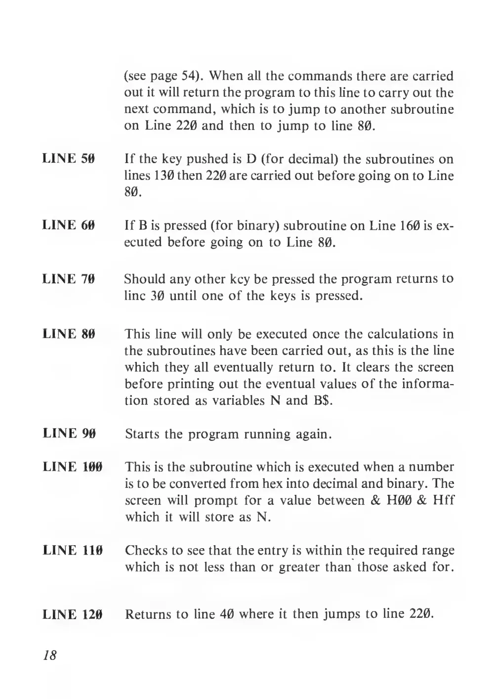
(see page 54). When all the commands there are carried
out
it will return the program to this line to carry out the
next command, which is to jump to another subroutine
on Line 220 and then to jump to line 80.
LINE 50
If the key pushed
is D (for decimal) the subroutines on
lines 130 then 220 are carried out before going on to Line
80.
LINE 60
If B is pressed (for binary) subroutine on Line 160 is ex-
ecuted before going on to Line 80.
LINE 70
Should any other key be pressed the program returns to
line 30 until one of the keys
is pressed.
LINE 80
This line will only be executed once the calculations in
the subroutines have been carried out, as this is the line
which they all eventually return to.
It clears the screen
before printing out the eventual values of the informa-
tion stored as variables N and B$.
LINE 90
Starts the program running again.
LINE 100
This is the subroutine which is executed when a number
is to be converted from hex into decimal and binary. The
screen will prompt for a value between & H00 & Hff
which
it will store as N.
LINE 110
Checks to see that the entry is within the required range
which
is not less than or greater than those asked for.
LINE 120
Returns to line 40 where
it then jumps to line 220.
18
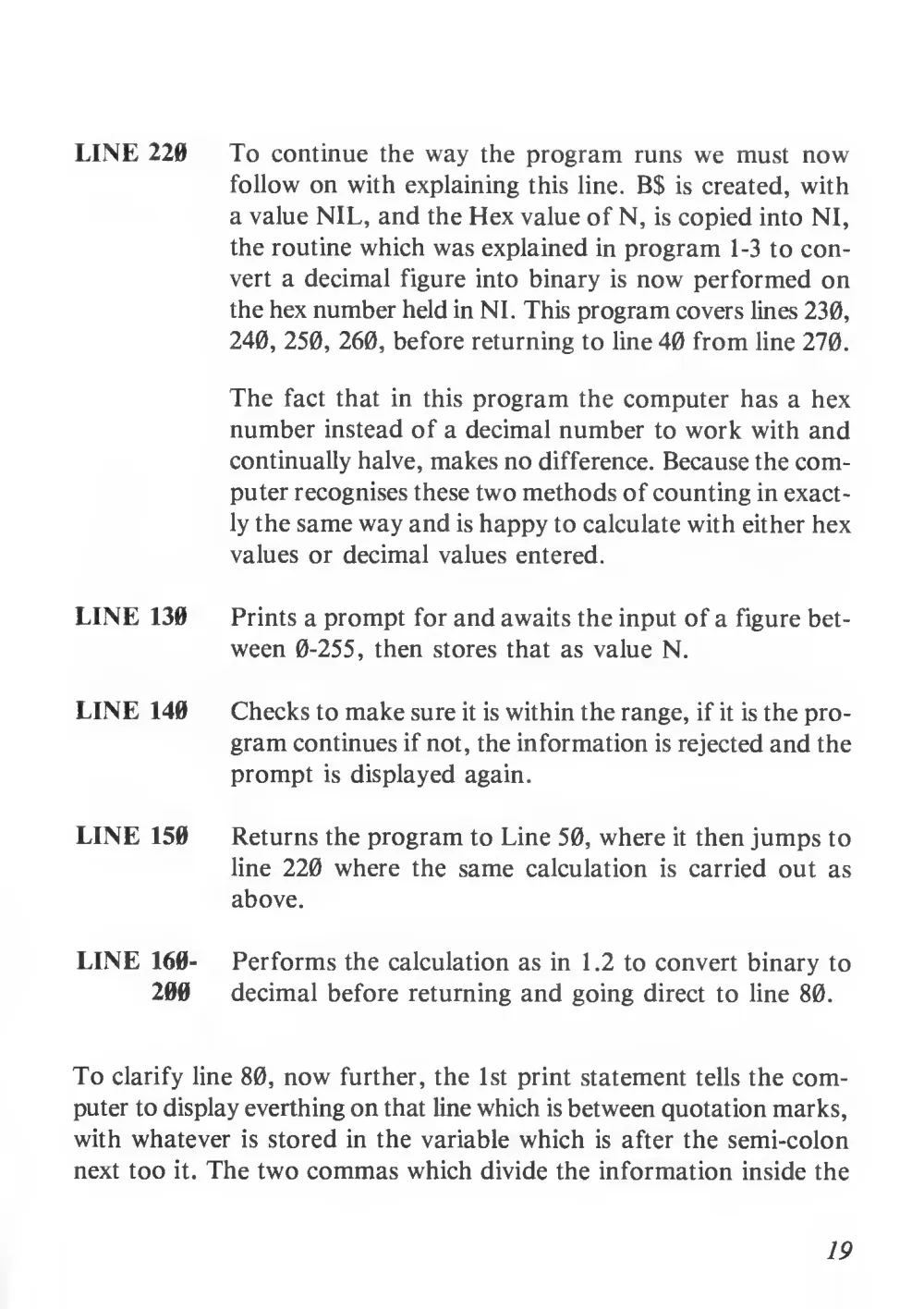
LINE 220
To continue the way the program runs we must now
follow on with explaining this line. B$
is created, with
a value NIL, and the Hex value of N,
is copied into NI,
the routine which was explained in program 1-3 to con-
vert a decimal figure into binary
is now performed on
the hex number held in NI. This program covers lines 230,
240, 250, 260, before returning to line 40 from line 270.
The fact that in
this program the computer has a hex
number instead of a decimal number to work with and
continually halve, makes no difference. Because the com-
puter recognises these two methods of counting in exact-
ly the same way and is happy to calculate with either hex
values or decimal values entered.
LINE 130
Prints a prompt for and awaits the input of a figure bet-
ween 0-255, then stores that as value N.
LINE 140
Checks to make sure it is within the range, if it is the pro-
gram continues if not, the information is rejected and the
prompt
is displayed again.
LINE 150
Returns the program to Line 50, where it then jumps to
line 220 where the same calculation
is carried out as
above.
LINE 160-
200
Performs the calculation as in 1.2 to convert binary to
decimal before returning and going direct to line 80.
To clarify line 80, now further, the
1st print statement tells the com-
puter to display everthing on that line which is between quotation marks,
with whatever
is stored in the variable which
is after the semi-colon
next too
it. The two commas which divide the information inside the
19
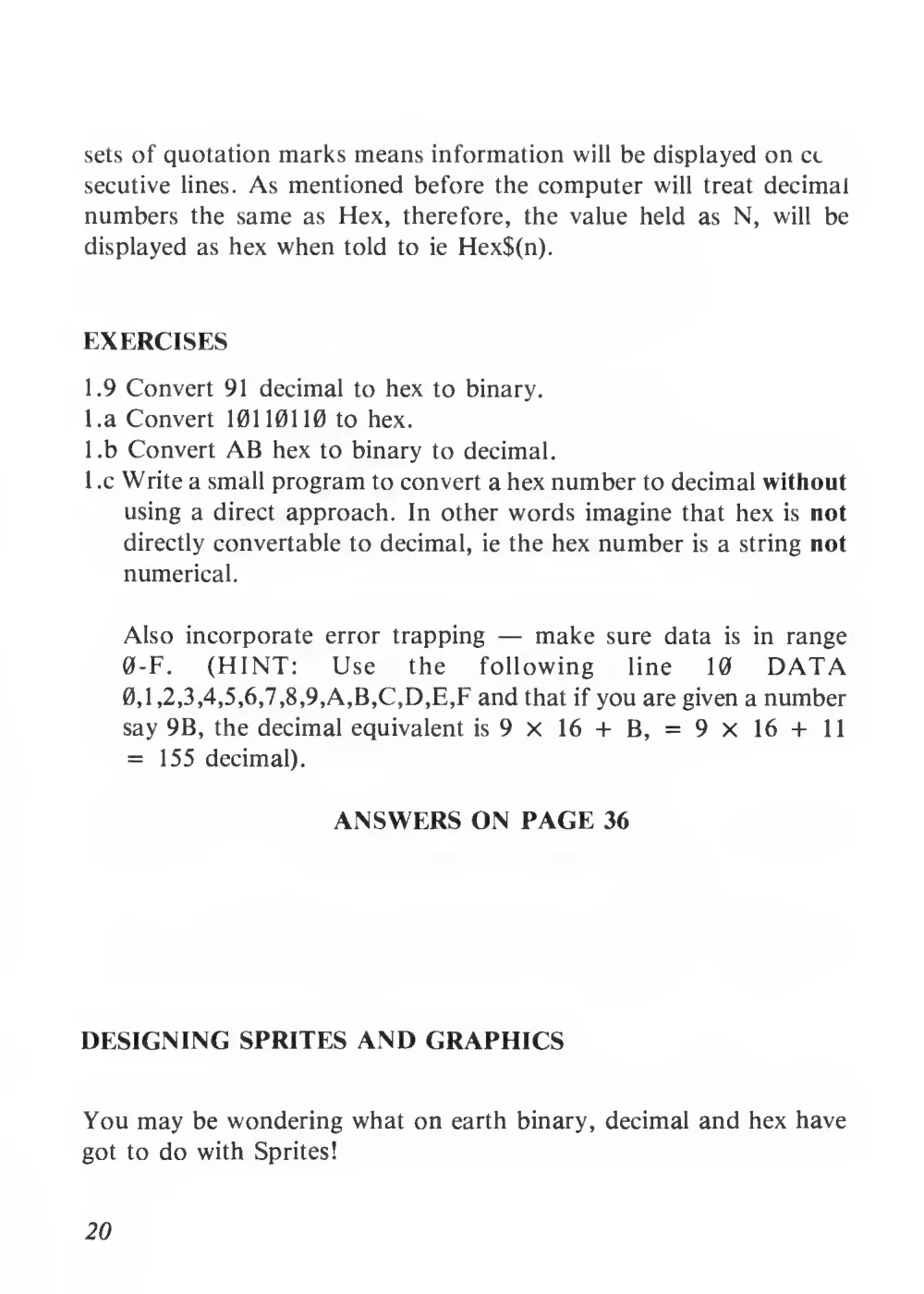
sets of quotation marks means information will be displayed on cc
secutive lines. As mentioned before the computer will treat decimal
numbers the same as Hex,
therefore,
the value held as N,
will be
displayed as hex when told to
ie Hex$(n).
EXERCISES
1.9 Convert 91 decimal to hex to binary,
l.a Convert 10110110 to hex.
I .b Convert AB hex to binary to decimal.
1 .c Write a small program to convert a hex number to decimal without
using a direct approach.
In other words imagine that hex
is not
directly convertable to decimal,
ie the hex number
is a string not
numerical.
Also incorporate error trapping — make sure data
is
in range
0-F.
(HINT:
Use
the
following
line
10
DATA
0,1 ,2,3,4,5,6,7,8,9,A,B,C,D,E,F and that if you are given a number
say 9B, the decimal equivalent is9x
16 +
B, =
9 X
16 +
11
=
155 decimal).
ANSWERS ON PAGE 36
DESIGNING SPRITES AND GRAPHICS
You may be wondering what on earth binary, decimal and hex have
got to do with Sprites!
20
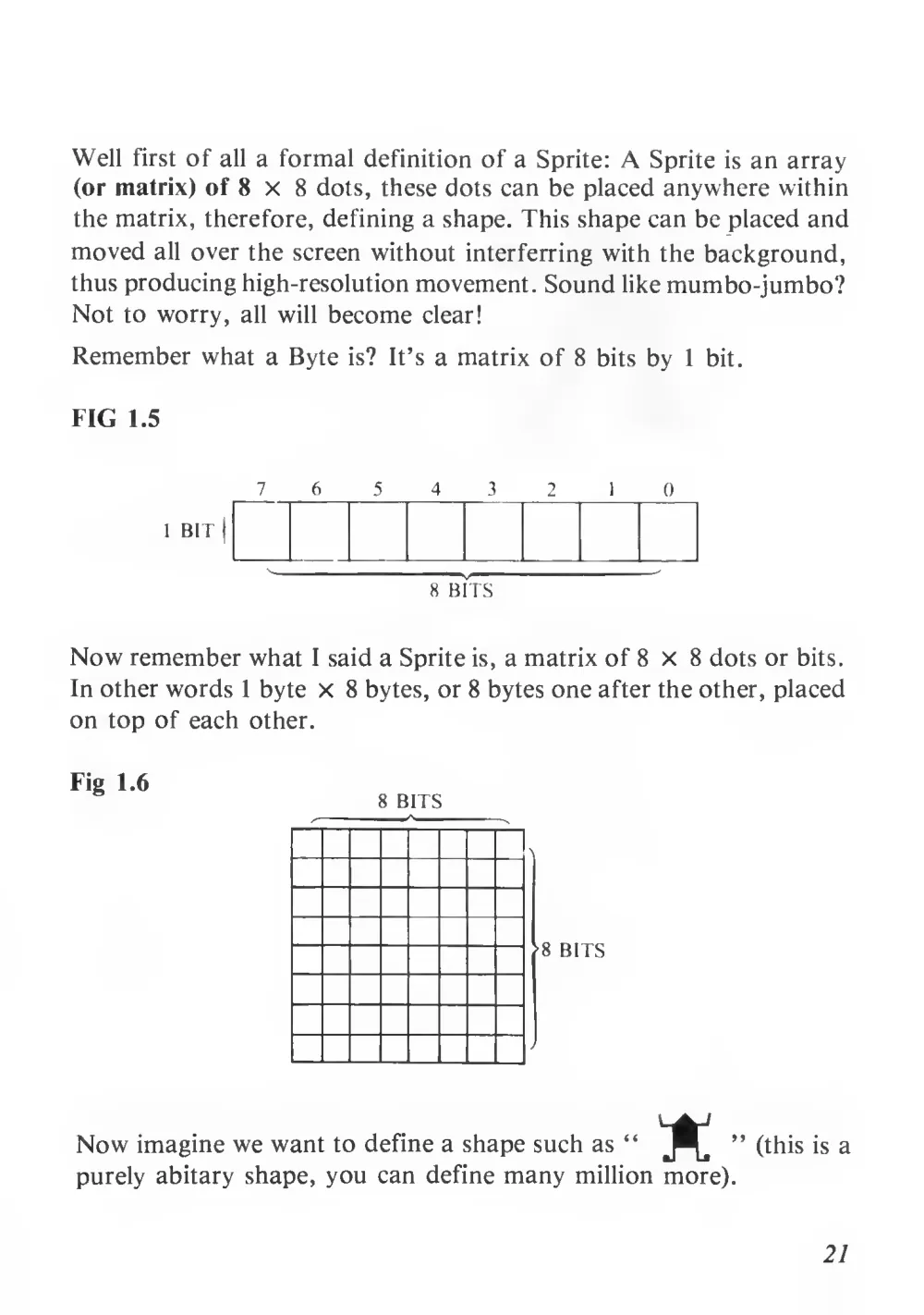
Well
first of all a formal definition of a Sprite: A Sprite
is an array
(or matrix) of 8 X
8 dots, these dots can be placed anywhere within
the matrix, therefore, defining a shape. This shape can be placed and
moved
all over the screen without interferring with the background,
thus producing high-resolution movement. Sound like mumbo-jumbo?
Not to worry,
all
will become clear!
Remember what a Byte is?
It’s a matrix of 8 bits by
1
bit.
FIG
1.5
7
6
5
4
3
2
1
0
1 BIT
|
Fbits
Now remember what
I said a Sprite is, a matrix of 8 X
8 dots or bits.
In other words
1 byte x
8 bytes, or 8 bytes one after the other, placed
on top of each other.
Fig
1.6
Now imagine we want to define a shape such as “ 'K
” (this
is a
purely abitary shape, you can define many million more).
21
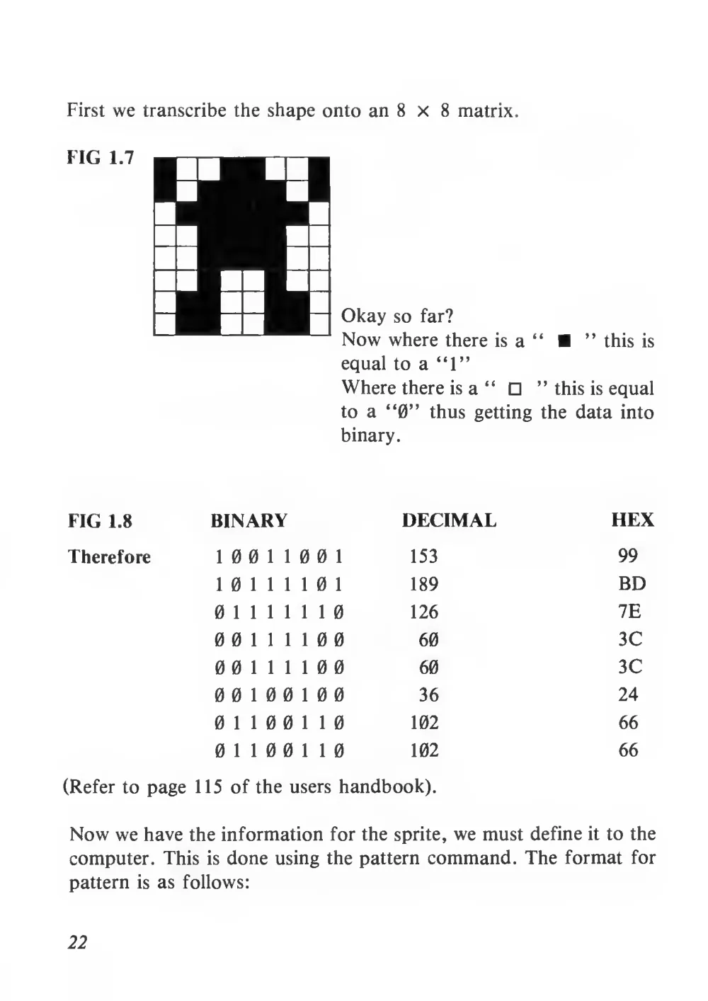
First we transcribe the shape onto an 8 X
8 matrix.
equal to a “1”
Where there is a “
” this is equal
to a “0”
thus getting the data into
binary.
FIG 1.8
BINARY
DECIMAL
HEX
Therefore
1 0 0
1
1 0 0
1
153
99
1 0
1
1
1
1 0
1
189
BD
0
1
1
1
1
1
1 0
126
7E
0 0
1
1
1
1 0 0
60
3C
0 0
1
1
1
1 0 0
60
3C
0 0
1 0 0
1 0 0
36
24
0
1
1 0 0
1
1 0
102
66
0
1
1 0 0
1
1 0
102
66
(Refer to page 115 of the users handbook).
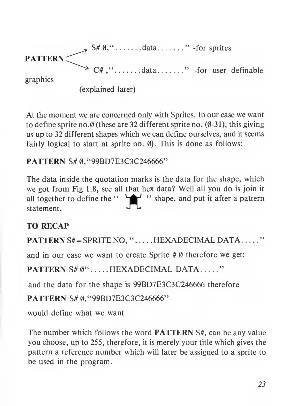
Now we have the information for the sprite, we must define
it to the
computer. This
is done using the pattern command. The format for
pattern
is as follows:
22
PATTERN
data
data
-for sprites
-for
user
definable
graphics
(explained later)
At the moment we are concerned only with Sprites. In our case we want
to define sprite no.0 (these are 32 different sprite no. (0-31), this giving
us up to 32 different shapes which we can define ourselves, and it seems
fairly logical to start
at sprite no.
0). This
is done as follows:
PATTERN S# 0,“99BD7E3C3C246666”
The data inside the quotation marks is the data for the shape, which
we got from Fig
1.8, see all that hex data? Well
all you do
is join
it
all together to define the “
'"A"*
” shape, and put
it after a pattern
statement.
TO RECAP
PATTERN S# = SPRITE NO, “
HEXADECIMAL DATA
”
and in our case we want to create Sprite
ft 0 therefore we get:
PATTERN S#0“
HEXADECIMAL DATA
”
and the data for the shape
is 99BD7E3C3C246666 therefore
PATTERN S# 0,“99BD7E3C3C246666”
would define what we want
The number which follows the word PATTERN S #, can be any value
you choose, up to 255, therefore,
it is merely your title which gives the
pattern a reference number which will later be assigned to a sprite to
be used in the program.
23
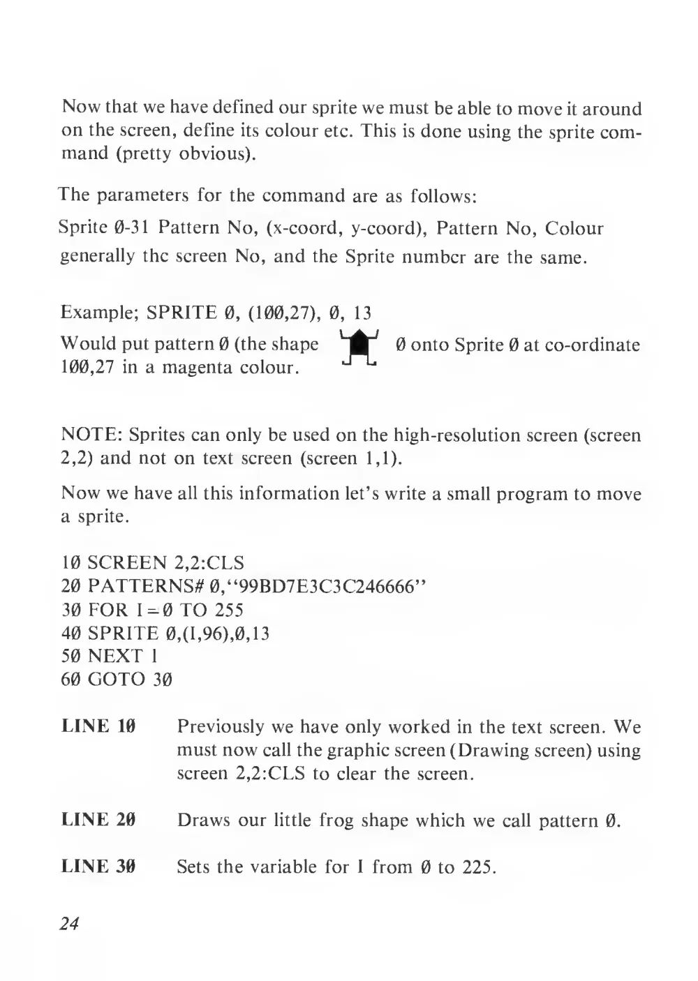
Now that we have defined our sprite we must be able to move it around
on the screen, define its colour etc. This is done using the sprite com-
mand (pretty obvious).
The parameters for the command are as follows:
Sprite 0-31
Pattern No, (x-coord, y-coord), Pattern No, Colour
generally the screen No, and the Sprite number are the same.
Example; SPRITE 0, (100,27),
0,
13
Would put pattern 0 (the shape
0 onto Sprite 0 at co-ordinate
100,27
in a magenta colour.
NOTE: Sprites can only be used on the high-resolution screen (screen
2,2) and not on
text screen (screen
1,1).
Now we have all this information let’s write a small program to move
a sprite.
10 SCREEN 2,2:CLS
20 PATTERNS# 0,“99BD7E3C3C246666”
30 FOR 1=0 TO 255
40 SPRITE 0,(1, 96),0,13
50 NEXT
I
60 GOTO 30
LINE 10
Previously we have only worked in the text screen. We
must now call the graphic screen (Drawing screen) using
screen 2,2:CLS to clear the screen.
LINE 20
Draws our
little frog shape which we call pattern 0.
LINE 30
Sets the variable for
1 from 0 to 225.
24
LINE 40
Assigns our pattern to the sprite number 0 and positions
it on the screen at
I on the X axis which
is currently 0
and 96 down and Y
axis which
is halfway down
the
screen.
LINE 50
Sends the program back and changes Y to
1
, which then
moves on to line 30 changing the position of the Sprite
one place along the x axis,
this continues until
1 = 255,
which means our frog moves right across the screen.
LINE 60
Sends the program back to the beginning where
it once
agains becomes 0. To increase the speed of movement
across the screen you use the step command on Line 30 ie.
FOR
I =0 to 255 STEP 2 or STEP 3 and so on. Ideally
the step should be divisible into the maximum co-ordinate
ie. 255.
To move the Sprite up the screen instead of across, try changing line
30 to FOR
I =
0 to
191 and Line 40 to SPRITE 0, (128, 1), 0,13.
Remember the co-ordinates for the X axis must not exceed 255 or For
the Y axis 151 which
is the maximum resolution.
PRECEDENCE OF SPRITES
If two sprites pass over each other, which Sprite takes precedence? ie.
which one passes behind the other? Well try the following program.
PROGRAM 1.7
10 SCREEN 2,2:CLS
20
PATTERNS
#0,
“99BD7E3C3C246666”:PATTERNS
#\,
“FFFFFFFFFFFFFFFF”
30 FOR
I =
0 to 255
25
40 SPRITE 0, (I,96),0,l :SPRITE
1, (255-1,96), 1,2
50 NEXT
I
60 GOTO 30
LINE 60
Calls the graphic screen, and clears
it.
LINE 20
Creates the Frog pattern 0 and a block pattern
1.
LINE 30
Sets the value of variable
I.
LINE 40
Assigns the frog to Sprite 0 and the block to Sprite
1.
LINE 50
As the value of
I increases the frog moves from left to
right. Because Sprites with lower title numbers are senior
to higher numbers the frog moves over the box, therefore,
Sprite 0 is the most significant sprite, Sprite 31
is the least
significant sprite.
Try the Following alteration to Program
1.7:
20 PATTERN$#I,“99BD7E3C3C246666”: PATTERNS# 0,“FFFFFFFFFFFFFFFF”
This time the box has precedence. This is because Sprite# 0 has greater
priority over Sprites#l, and Sprite#l has priority over Sprite#2 etc.
.
.
It is extremely important that you understand the principle of priority
and precedence.
So to sum up:
SPRITE#0 has priority over Sprite#l
has priority over Sprite#2 has
priority over Sprite#3 has priority over Sprite#4
Sprite#30 has
priority over Sprite#31.
UNDERSTAND?
GOOD!
(Read
Page
121-122
Sega
owners
Handbook).
26
MAGNIFICATION, LARGER
SPRITES AND THE MAG
COMMAND
Once you have defined your sprite
it
is actually possible to double its
size by using the MAG command. Normally MAG
is
set
to 0,
this
means, “draw the sprite on the screen at normal size”, but if you enter
MAG 2, you can double the size, try this program.
PROGRAM
1.8
10 SCREEN 2,2:CLS
20 PATTERNS# 0,“99BD7E3C3C246666”
30 MAG 2: FOR
I = 0 TO
191
40 SPRITE 0, (128, 1),0,13
50 NEXT
I
60 GOTO 30
LINE 10
LINE 20
LINE 30-50
LINE 60
Call high resolution screen. Clear Screen.
DEFINE SPRITE 0.
Cause the Sprite to double in size, move Sprite# 0, down
centre of screen.
Repeat movement.
See how big the Sprite is?
It has actually doubled in size! Not bad is
it?! Try altering the MAG command in Line 30 to mag 0 to get back
to normal size and re-run program to contrast the difference.
Now you are probably wondering, “Okay we have MAG 0 and MAG
2, but what has happened to MAG 1?”. Well Mag
1 does exist and
so does another Mag, MAG3. These two enable you to create one large
sprite out of 4
little ones.
27
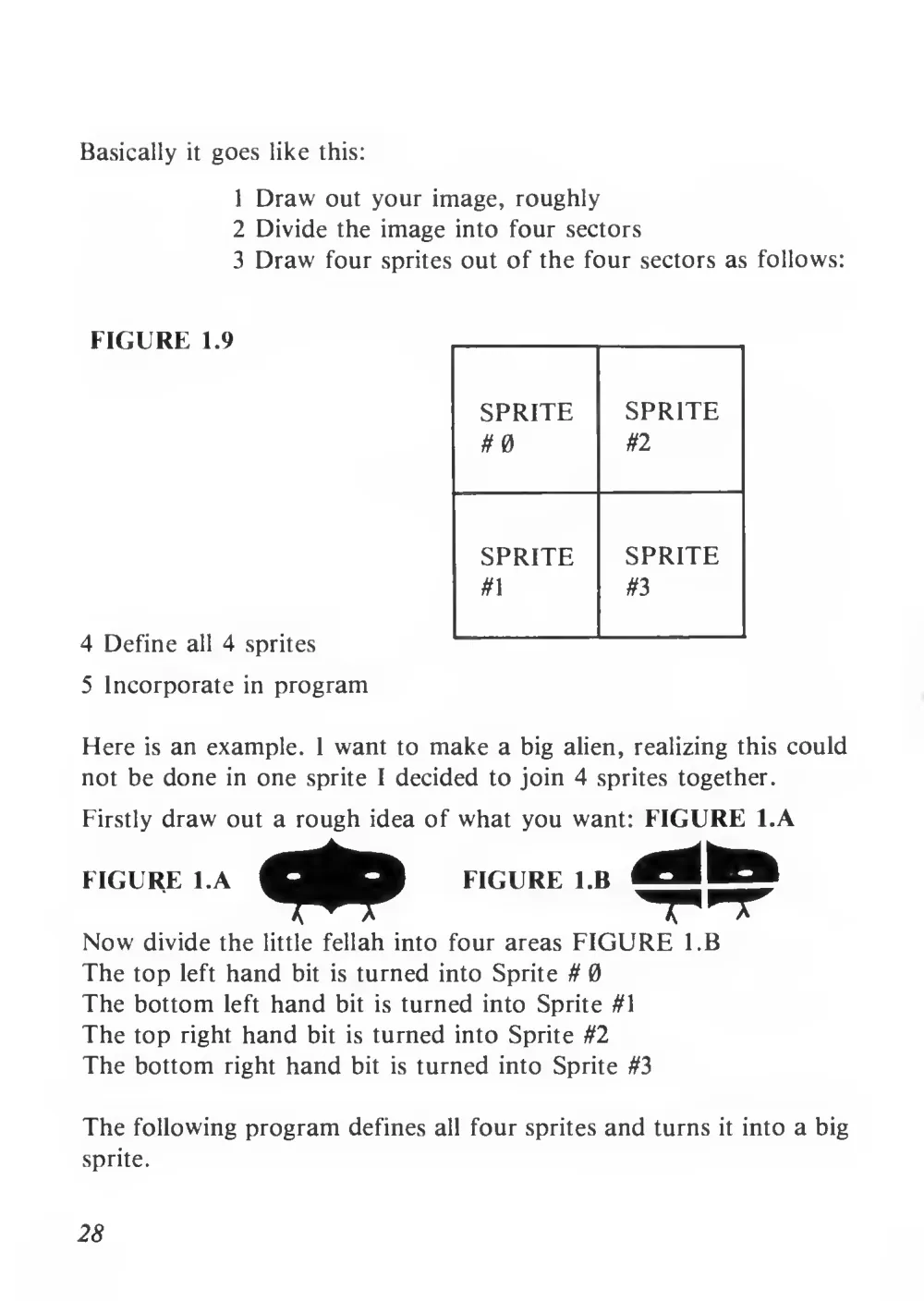
Basically
it goes like this:
1 Draw out your image, roughly
2 Divide the image into four sectors
3 Draw four sprites out of the four sectors as follows:
FIGURE
1.9
4 Define
all 4 sprites
5 Incorporate
in program
SPRITE
#0
SPRITE
#2
SPRITE
#1
SPRITE
#3
Here
is an example.
I want to make a big alien, realizing this could
not be done in one sprite
I decided to join 4 sprites together.
Firstly draw out a rough idea of what you want: FIGURE l.A
FIGURE l.A
Now divide the
little fellah into four areas FIGURE l.B
The top
left hand
bit
is turned into Sprite # 0
The bottom
left hand
bit
is turned into Sprite #1
The top right hand
bit
is turned into Sprite #2
The bottom right hand
bit
is turned into Sprite #3
The following program defines all four sprites and turns
it into a big
sprite.
28
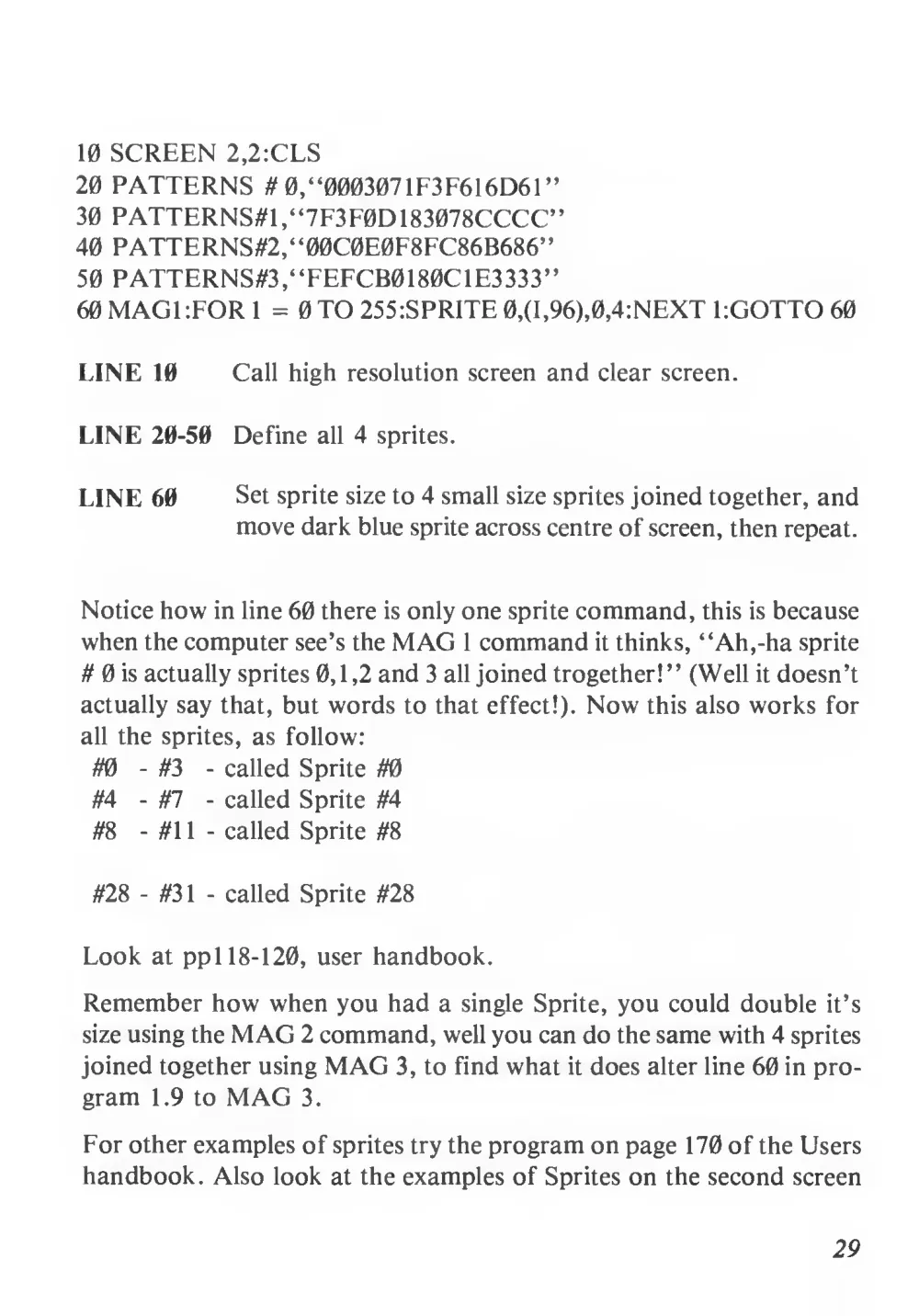
10 SCREEN 2,2:CLS
20 PATTERNS # 0, “000307 1F3F616D61”
30 PATTERNS#1 ,“7F3F0D183078CCCC”
40 PATTERNS#2,“00C0E0F8FC86B686”
50 PATTERNS^, “FEFCB0180C1E3333”
60 MAGI :FOR
I = 0 TO 255:SPRITE 0,(I,96),0,4:NEXT EGOTTO 60
LINE 10
Call high resolution screen and clear screen.
LINE 20-50
Define all 4 sprites.
LINE 60
Set sprite size to 4 small size sprites joined together, and
move dark blue sprite across centre of screen, then repeat.
Notice how in line 60 there is only one sprite command, this is because
when the computer see’s the MAG
1 command
it thinks, “Ah, -ha sprite
# 0 is actually sprites 0,1,2 and 3 all joined trogether!” (Well
it doesn’t
actually say that, but words to that effect!). Now this also works for
all the sprites, as follow:
#0
- #3
- called Sprite #0
#4
- #7
- called Sprite #4
#8
- #1
1
- called Sprite #8
#28
- #31
- called Sprite #28
Look at ppl 18-120, user handbook.
Remember how when you had a single Sprite, you could double
it’s
size using the MAG 2 command, well you can do the same with 4 sprites
joined together using MAG 3, to find what it does alter line 60 in pro-
gram
1.9 to MAG
3.
For other examples of sprites try the program on page 170 of the Users
handbook. Also look at the examples of Sprites on the second screen
29
of the “Basic Games Programming” tape. The first Sprite (the box)
is an example of Mag 0, the red sprite that goes from bottom right to
top left
is an example of Mag
1
, and the blue sprite that rises to the
top of the screen, and then goes to the bottom right
is an example of
MAG
3. The above part of the program
lies between lines 250-350.
Once this page is over you are given a chance to design your own sprites
by using the next point of the program called “Create-a-sprite”.
You first enter whether you want to define a sprite or a user-definable
graphic. What’s a user definable graphic (UDG)?
1 here you say. Well
a UDG
is really a sprite to a certain extent in that you can define
it,
but that
is where the similarity ends. A sprite
is designed on an 8 x
8 matrix, a UDG
is on a 6 X
8 matrix, notice how a sprite doesn’t
leave a
trail behind
it well a udg does, there are 32 sprites and 256
UDG’s, a Sprite can only be printed on the high resolution screen, a
UDG can go on either the text screen or the high-res screen, and final-
ly the entire character set (see page: 154, 155 users handbook) is nothing
more than a load of UDG’s, and this means that you can define your
own letters as you see fit, in exactly the same way as you would a Sprite.
The only difference
is in the PATTERN command.
Remember when we define a sprite we used the following format:
PATTERN S#Sprite No,“
Hex Data
”
Well the only difference between the above format and that for the
defining of UDG’s
is as follows:
PATTERN C#Character No, “
Hex Data
”
So lets take an example, look at page 155 of the Users handbook. Now
look at character No. 207, the pound sterling sign,
If you print
the character on the screen (by using PRINT CHR$(207)
) you will see
it is not really a very accurate representation of the sign, so why not
redefine it? Well this is how it is done it is exactly the same as defining
30
a sprite just that you use a 6 x
8 matrix instead of an 8 x
8 matrix.
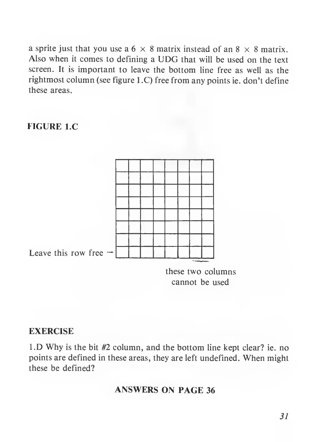
Also when
it comes to defining a UDG that will be used on the text
screen.
It
is important to
leave the bottom
line
free as well as the
rightmost column (see figure
1 .C) free from any points ie. don’t define
these areas.
FIGURE l.C
Leave this row free —
these two columns
cannot be used
EXERCISE
l.D Why
is the bit #2 column, and the bottom line kept clear?
ie. no
points are defined in these areas, they are left undefined. When might
these be defined?
ANSWERS ON PAGE 36
31
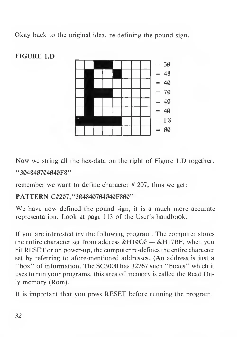
Okay back to the original idea, re-defining the pound sign.
FIGURE l.D
=
30
= 48
= 40
= 70
= 40
= 40
= F8
= 00
Now we string
all the hex-data on the right of Figure l.D together.
“304840704040F8”
remember we want to define character # 207, thus we get:
PATTERN C#207
, “304840704040F800”
We have now defined the pound
sign,
it
is a much more accurate
representation. Look
at page 113 of the User’s handbook.
If you are interested try the following program. The computer stores
the entire character set from address &H10C0 — &FU7BF, when you
hit RESET or on power-up, the computer re-defines the entire character
set by referring to afore-mentioned addresses. (An address
is just a
“box” of information. The SC3000 has 32767 such “boxes” which
it
uses to run your programs, this area of memory is called the Read On-
ly memory (Rom).
It
is important that you press RESET before running the program.
32
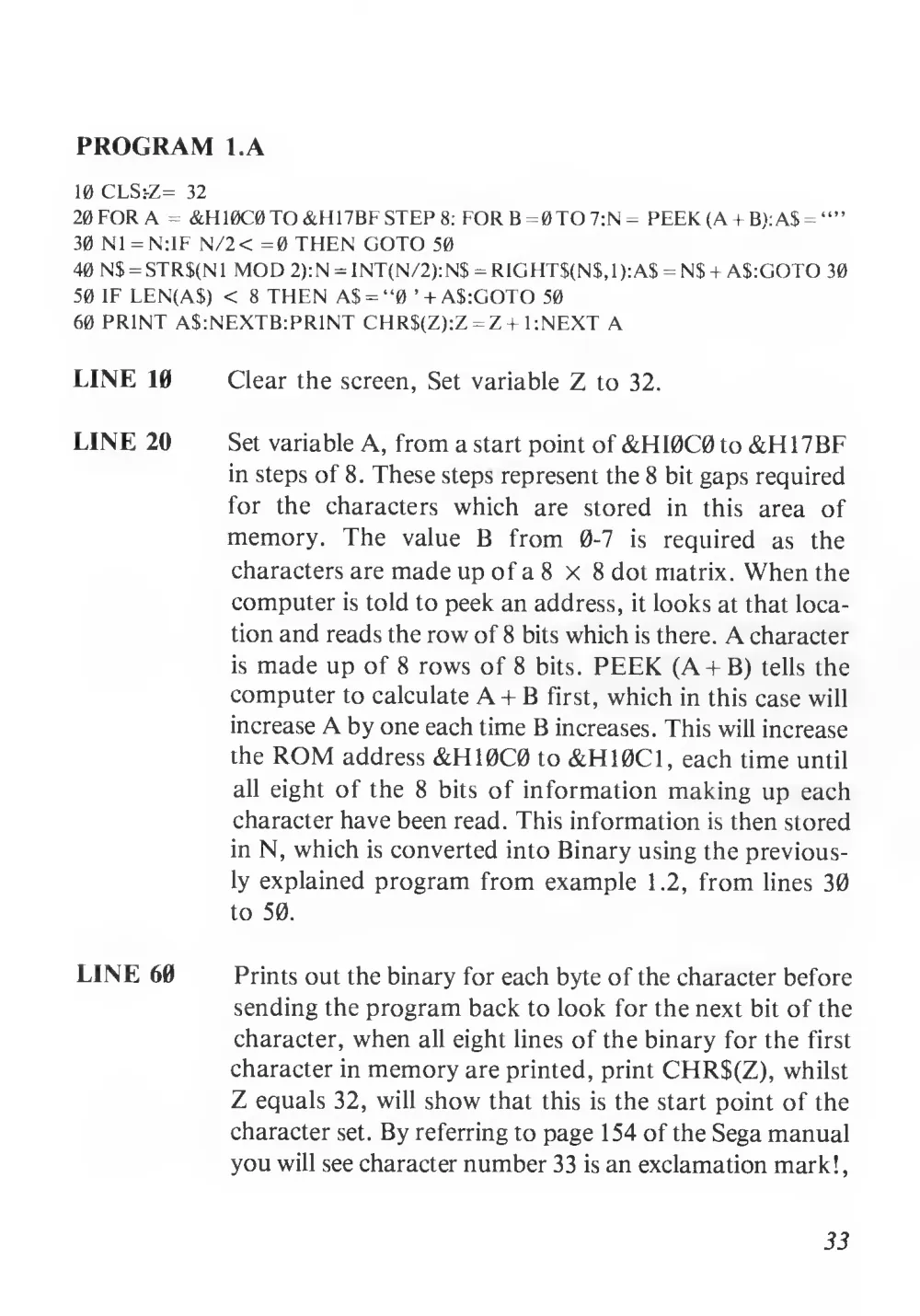
PROGRAM l.A
10 CLS:-Z=
32
20 FOR A = &H10C0TO &H17BF STEP 8: FOR B=0TO7:N = PEEK (A + B):A$ = “”
30 N1 =N:IF N/2< =0 THEN GOTO 50
40 N$ = STR$(N1 MOD 2):N = INT(N/2):N$ = RIGHT$(N$,1):A$ = N$ + A$:GOTO 30
50 IF LEN(A$) <
8 THEN A$ = “0
’ + A$:GOTO 50
60 PRINT AS: NEXT B: PRINT CHR$(Z):Z = Z +
1 :NEXT A
LINE 10
Clear the screen, Set variable Z to 32.
LINE 20
Set variable A, from a start point of&HI0C0 to &H17BF
in steps of 8. These steps represent the 8 bit gaps required
for
the
characters
which
are
stored
in
this
area
of
memory.
The
value B
from
0-7
is
required
as
the
characters are made up of a 8 x
8 dot matrix. When the
computer
is told to peek an address,
it looks at that loca-
tion and reads the row of 8 bits which is there. A character
is made up of 8 rows of 8
bits. PEEK (A+ B) tells the
computer to calculate A + B first, which in this case will
increase A by one each time B increases. This will increase
the ROM address &H10C0 to &H10C1, each time until
all eight of the 8
bits of information making up each
character have been read. This information is then stored
in N, which is converted into Binary using the previous-
ly explained program from example
1 .2, from lines 30
to 50.
LINE 60
Prints out the binary for each byte of the character before
sending the program back to look for the next bit of the
character, when all eight lines of the binary for the first
character in memory are printed, print CHR$(Z), whilst
Z equals 32, will show that this is the start point of the
character set. By referring to page 154 of the Sega manual
you will see character number 33 is an exclamation mark!
,
33
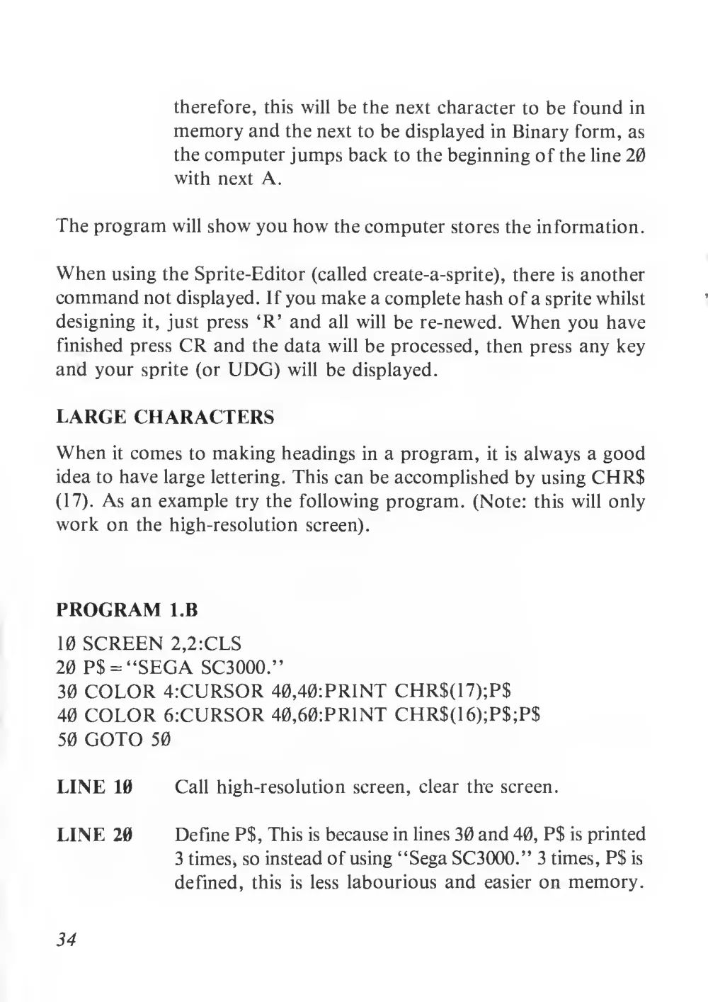
therefore, this will be the next character to be found in
memory and the next to be displayed in Binary form, as
the computer jumps back to the beginning of the line 20
with next A.
The program will show you how the computer stores the information.
When using the Sprite-Editor (called create-a-sprite), there is another
command not displayed. If you make a complete hash of a sprite whilst
designing
it, just press ‘R’ and
all will be re-newed. When you have
finished press CR and the data will be processed, then press any key
and your sprite (or UDG) will be displayed.
LARGE CHARACTERS
When
it comes to making headings in a program,
it
is always a good
idea to have large lettering. This can be accomplished by using CHR$
(17). As an example try the following program. (Note: this will only
work on the high-resolution screen).
PROGRAM l.B
10 SCREEN 2,2:CLS
20 P$ = “SEGA SC3000.”
30 COLOR 4:CURSOR 40,40:PRINT CHR$(17);P$
40 COLOR 6.-CURSOR 40,60:PRINT CHR$(16);P$;P$
50 GOTO 50
LINE 10
Call high-resolution screen, clear the screen.
LINE 20
Define P$, This is because in lines 30 and 40, P$ is printed
3 times* so instead of using “Sega SC3000.” 3 times, P$ is
defined,
this
is less labourious and easier on memory.
34
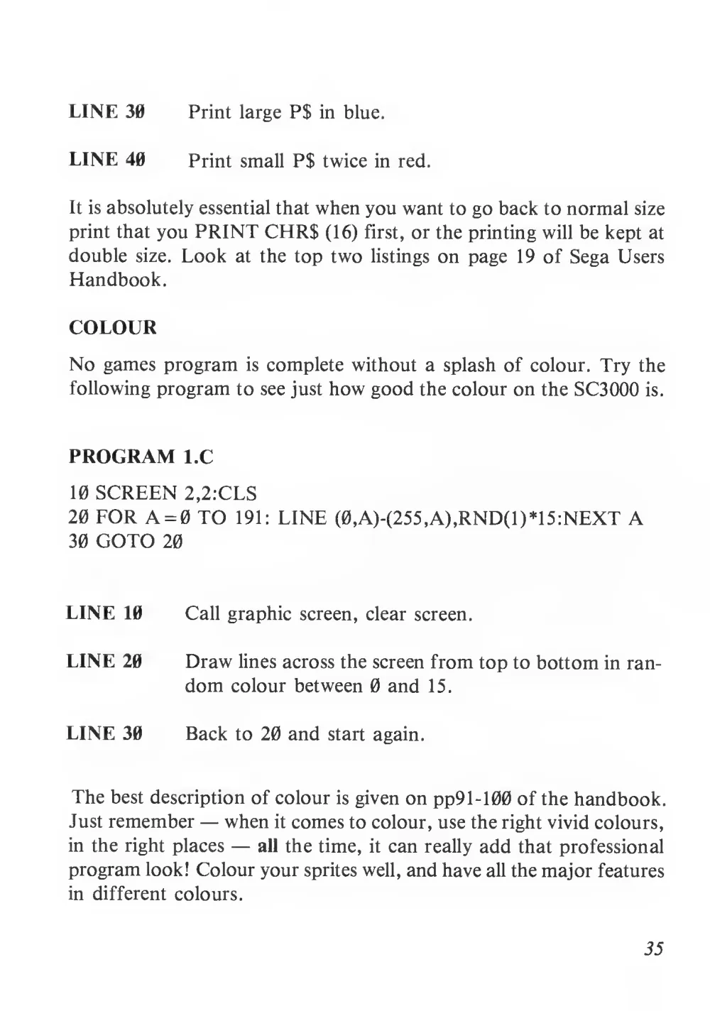
LINE 30
Print large P$ in blue.
LINE 40
Print small P$ twice in red.
It is absolutely essential that when you want to go back to normal size
print that you PRINT CHR$ (16) first, or the printing will be kept at
double
size. Look
at the top two
listings on page 19 of Sega Users
Handbook.
COLOUR
No games program
is complete without a splash of colour. Try the
following program to see just how good the colour on the SC3000
is.
PROGRAM l.C
10 SCREEN 2,2:CLS
20 FOR A = 0 TO
191: LINE (0,A)-(255,A),RND(1)*15:NEXT A
30 GOTO 20
LINE 10
Call graphic screen, clear screen.
LINE 20
Draw lines across the screen from top to bottom in ran-
dom colour between 0 and
15.
LINE 30
Back to 20 and start again.
The best description of colour is given on pp91-100 of the handbook.
Just remember — when it comes to colour, use the right vivid colours,
in the right places —
all the time,
it can really add that professional
program look! Colour your sprites well, and have all the major features
in different colours.
35
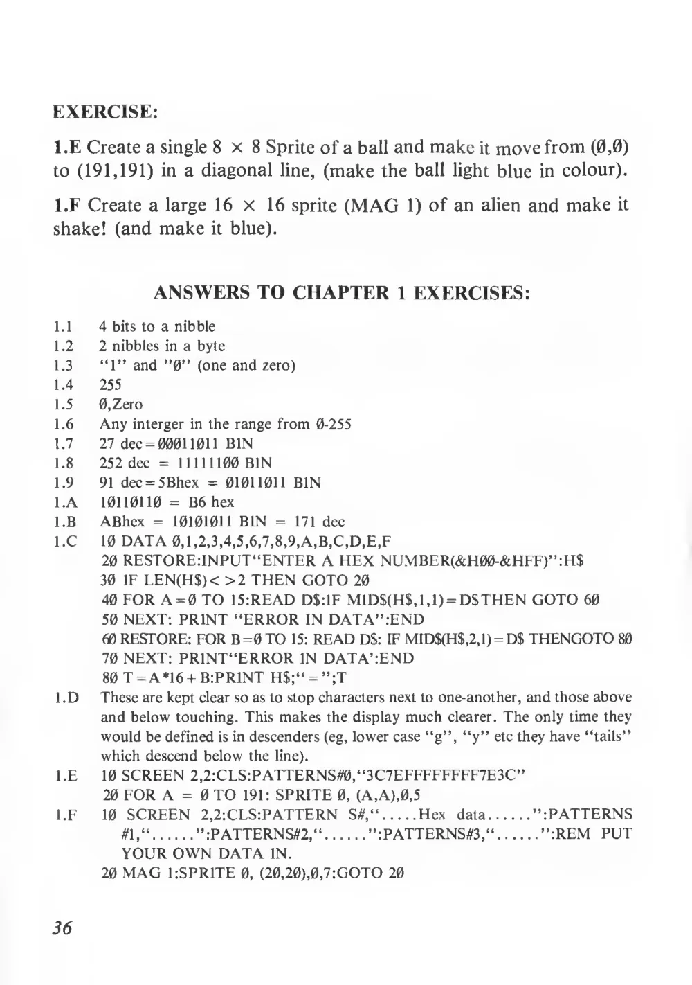
EXERCISE:
l.E Create a single 8x8 Sprite of a ball and make it move from (0,0)
to (191,191) in a diagonal line, (make the ball light blue in colour).
l.F Create a large 16 x
16 sprite (MAG
1) of an alien and make
it
shake! (and make
it blue).
ANSWERS TO CHAPTER
1 EXERCISES:
1.1
4 bits to a nibble
1.2
2 nibbles in a byte
1.3
“1” and ”0” (one and zero)
1.4
255
1.5
0,Zero
1.6
Any interger in the range from 0-255
1.7
27 dec = 0001 1011 BIN
1.8
252 dec =
11111100 BIN
1.9
91 dec = 5Bhex = 01011011 BIN
l.A
10110110 = B6 hex
l.B
ABhex =
10101011 BIN =
171 dec
l.C
10 DATA 0,1,2,3,4,5,6,7,8,9,A,B,C,D,E,F
20 RESTORE: INPUT“ENTER A HEX NUMBER(&H00-&HFF)”:H$
30
IF LEN(H$)< >2 THEN GOTO 20
40 FOR A = 0 TO 15:READ D$:IF MID$(H$,1,1) = D$THEN GOTO 60
50 NEXT: PRINT “ERROR IN DATA”:END
60 RESTORE: FORB=0TO 15: READ D$: IF MID$(H$,2,1) = D$ THENGOTO 80
70 NEXT: PRINT“ERROR IN DATA’:END
80 T = A*16 + B:PRINT H$;“ = ”;T
1 .D
These are kept clear so as to stop characters next to one-another, and those above
and below touching. This makes the display much clearer. The only time they
would be defined is in descenders (eg, lower case “g”, “y” etc they have “tails”
which descend below the line).
l.E
10 SCREEN 2,2:CLS:PATTERNS#0,“3C7EFFFFFFFF7E3C”
20 FOR A = 0 TO
191: SPRITE 0, (A,A),0,5
l.F
10 SCREEN 2,2:CLS:PATTERN
S#,“
Hex
data
”:PATTERNS
#1,“
”:PATTERNS#2,“
”:PATTERNS03,“
”:REM PUT
YOUR OWN DATA IN.
20 MAG ESPRITE 0, (20,20),0,7:GOTO 20
36
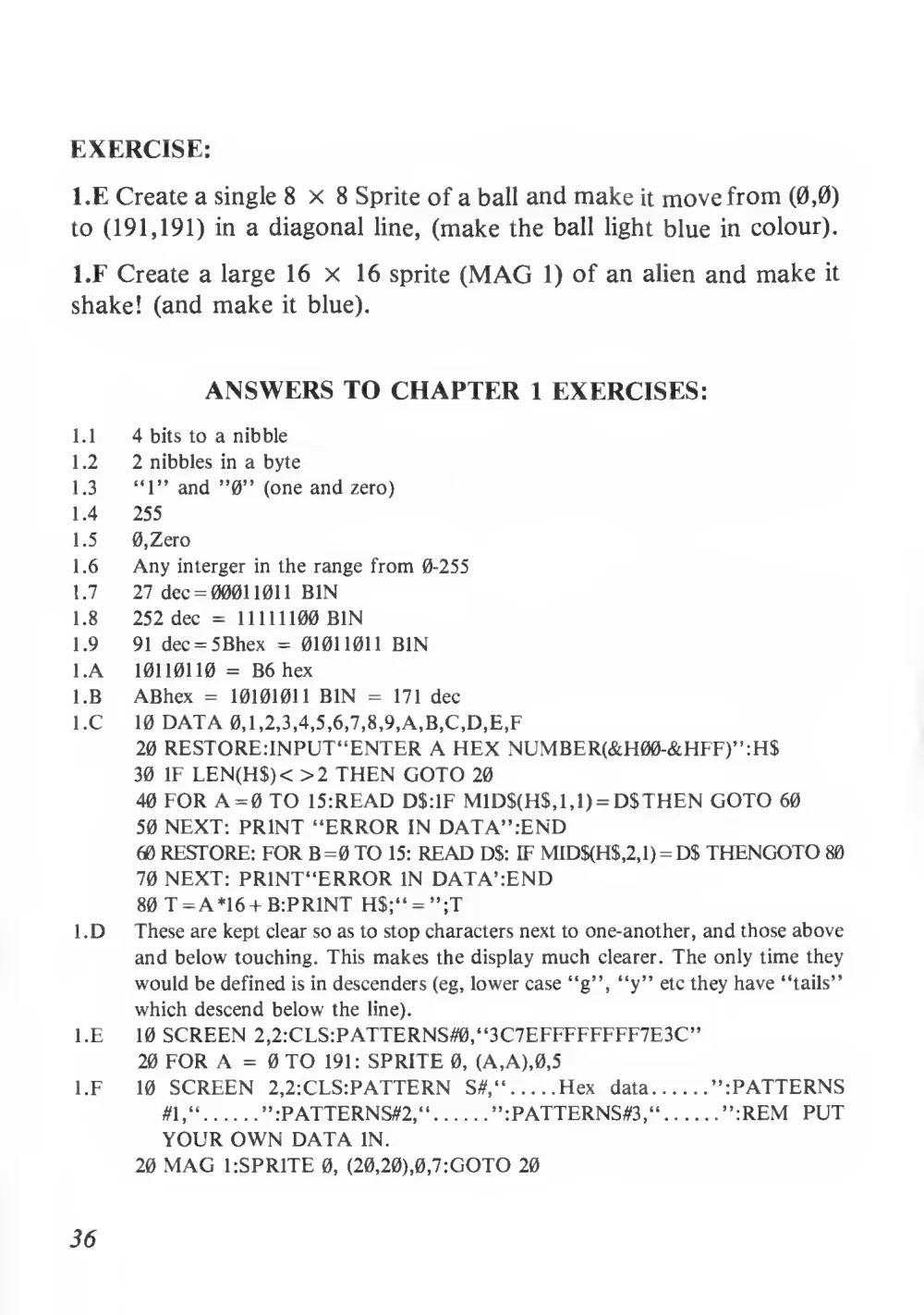
EXERCISE:
l.E Create a single 8x8 Sprite of a ball and make it move from (0,0)
to (191,191) in a diagonal line, (make the ball light blue in colour).
l.F Create a large 16 x
16 sprite (MAG
1) of an alien and make
it
shake! (and make
it blue).
ANSWERS TO CHAPTER
1 EXERCISES:
1.1
4 bits to a nibble
1.2
2 nibbles in a byte
1.3
“1” and ”0” (one and zero)
1.4
255
1.5
0,Zero
1.6
Any interger in the range from 0-255
1.7
27 dec = 0001 1011 BIN
1.8
252 dec =
11111100 BIN
1.9
91 dec = 5Bhex = 01011011 BIN
l.A
10110110 = B6 hex
l.B
ABhex =
10101011 BIN =
171 dec
l.C
10 DATA 0,1,2,3,4,5,6,7,8,9,A,B,C,D,E,F
20 RESTORE: INPUT“ENTER A HEX NUMBER(&H00-&HFF)”:H$
30
IF LEN(H$)< >2 THEN GOTO 20
40 FOR A = 0 TO 15:READ D$:IF MID$(H$,1,1) = D$THEN GOTO 60
50 NEXT: PRINT “ERROR IN DATA”:END
60 RESTORE: FORB=0TO 15: READ D$: IF MID$(H$,2,1) = D$ THENGOTO 80
70 NEXT: PRINT“ERROR IN DATA’:END
80 T = A*16 + B:PRINT H$;“ = ”;T
1 .D
These are kept clear so as to stop characters next to one-another, and those above
and below touching. This makes the display much clearer. The only time they
would be defined is in descenders (eg, lower case “g”, “y” etc they have “tails”
which descend below the line).
l.E
10 SCREEN 2,2:CLS:PATTERNS#0,“3C7EFFFFFFFF7E3C”
20 FOR A = 0 TO
191: SPRITE 0, (A,A),0,5
l.F
10 SCREEN 2,2:CLS:PATTERN
S#,“
Hex
data
”:PATTERNS
#1,“
”:PATTERNS#2,“
”:PATTERNS03,“
”:REM PUT
YOUR OWN DATA IN.
20 MAG ESPRITE 0, (20,20),0,7:GOTO 20
36
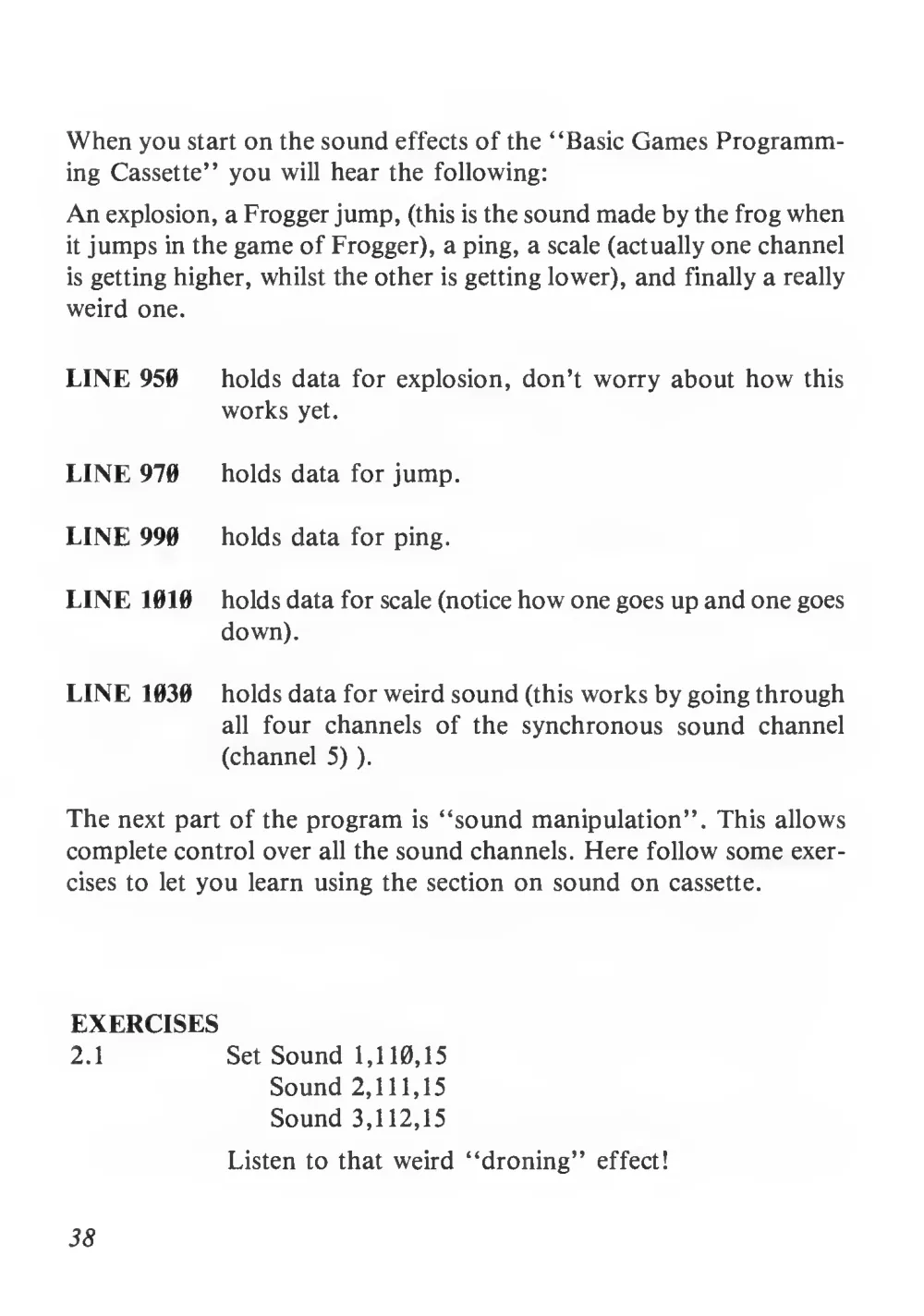
When you start on the sound effects of the “Basic Games Programm-
ing Cassette” you will hear the following:
An explosion, a Frogger jump, (this is the sound made by the frog when
it jumps in the game of Frogger), a ping, a scale (actually one channel
is getting higher, whilst the other is getting lower), and finally a really
weird one.
LINE 950
holds data for explosion, don’t worry about how this
works yet.
LINE 970
holds data for jump.
LINE 990
holds data for ping.
LINE 1010
holds data for scale (notice how one goes up and one goes
down).
LINE 1030
holds data for weird sound (this works by going through
all
four channels of the synchronous sound channel
(channel 5)
).
The next part of the program
is “sound manipulation”. This allows
complete control over all the sound channels. Here follow some exer-
cises to
let you learn using the section on sound on cassette.
EXERCISES
2.1
Set Sound 1,110,15
Sound 2,111,15
Sound 3,112,15
Listen to that weird “droning” effect!
38
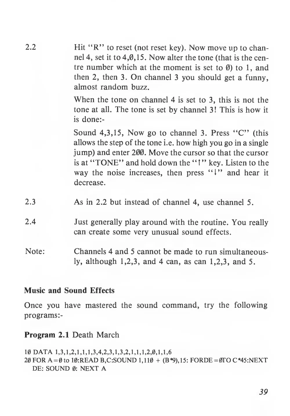
2.2
Hit “R” to reset (not reset key). Now move up to chan-
nel 4, set it to 4,0,15. Now alter the tone (that is the cen-
tre number which at the moment
is set to 0) to
1
, and
then 2, then
3. On channel 3 you should get a funny,
almost random buzz.
When the tone on channel 4
is set to 3, this
is not the
tone at all. The tone is set by channel 3! This
is how
it
is done:-
Sound 4,3,15, Now go to channel
3.
Press “C”
(this
allows the step of the tone i.e. how high you go in a single
jump) and enter 200. Move the cursor so that the cursor
is at “TONE” and hold down the “
t ” key. Listen to the
way the noise
increases,
then
press “1” and hear
it
decrease.
2.3
As in 2.2 but instead of channel 4, use channel
5.
2.4
Just generally play around with the routine. You really
can create some very unusual sound effects.
Note:
Channels 4 and 5 cannot be made to run simultaneous-
ly, although
1,2,3, and 4 can, as can 1,2,3, and 5.
Music and Sound Effects
Once you have mastered
the sound command,
try
the
following
programs:-
Program 2.1 Death March
10 DATA
1,3, 1,2, 1,1, 1,3,4, 2, 3, 1,3,2,1, 1,1,2, 0,1, 1,6
20 FOR A =0 to 10:READ B,C:SOUND 1,110 + (B*9),15: FORDE = 0TO C*45:NEXT
DE: SOUND 0: NEXT A
39
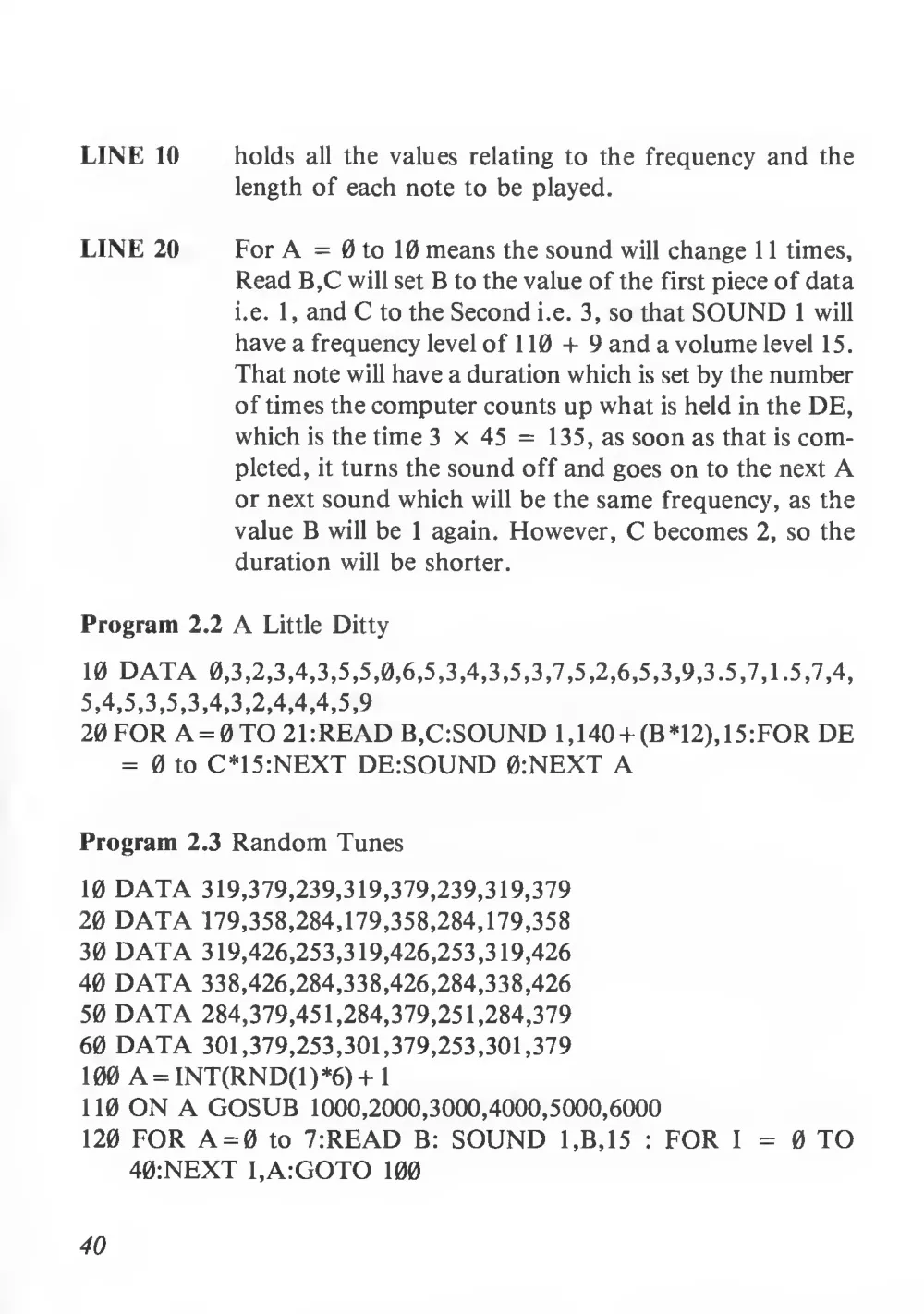
LINE 10
holds
all the values relating to the frequency and the
length of each note to be played.
LINE 20
For A = 0 to 10 means the sound will change
1 1 times,
Read B,C will set B to the value of the first piece of data
i.e.
1, and C to the Second i.e. 3, so that SOUND
1 will
have a frequency level of
1 10 + 9 and a volume level 15.
That note will have a duration which is set by the number
of times the computer counts up what is held in the DE,
which is the time 3 x 45 =
135, as soon as that is com-
pleted,
it turns the sound off and goes on to the next A
or next sound which will be the same frequency, as the
value B will be
1 again. However, C becomes 2, so the
duration will be shorter.
Program 2.2 A Little Ditty
10 DATA
0,3, 2, 3, 4, 3, 5, 5,0,6, 5, 3, 4, 3, 5, 3, 7, 5, 2, 6, 5, 3, 9, 3. 5, 7, 1.5, 7, 4,
5, 4, 5, 3, 5, 3, 4, 3, 2, 4, 4, 4, 5,
9
20 FOR A = 0TO 21:READ B,C:SOUND 1,140 + (B*12),15:FOR DE
= 0 to C*15:NEXT DE:SOUND 0:NEXT A
Program 2.3 Random Tunes
10 DATA 319,379,239,319,379,239,319,379
20 DATA 179,358,284,179,358,284,179,358
30 DATA 319,426,253,319,426,253,319,426
40 DATA 338,426,284,338,426,284,338,426
50 DATA 284,379,451,284,379,251,284,379
60 DATA 301,379,253,301,379,253,301,379
100 A = INT(RND(1)*6)+
1
110 ON A GOSUB 1000,2000,3000,4000,5000,6000
120 FOR A = 0 to 7:READ B: SOUND
1,B,15
: FOR
I =
0 TO
40:NEXT I,A:GOTO 100
40
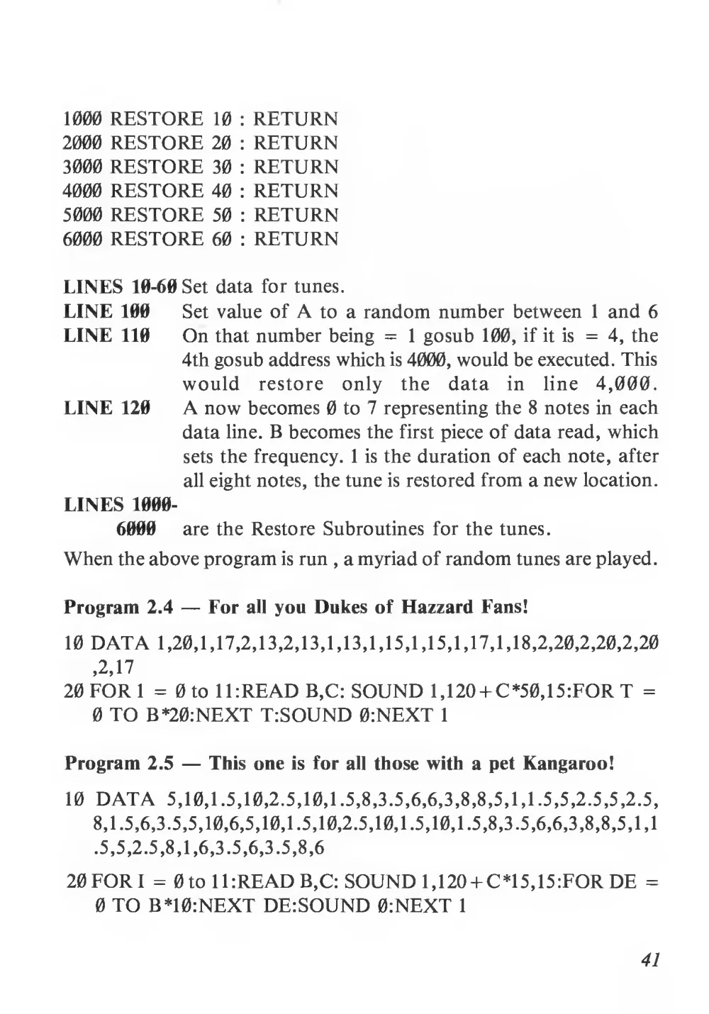
1000 RESTORE 10
: RETURN
2000 RESTORE 20
: RETURN
3000 RESTORE 30
: RETURN
4000 RESTORE 40
: RETURN
5000 RESTORE 50
: RETURN
6000 RESTORE 60
: RETURN
LINES 10-60 Set data for tunes.
LINE 100
Set value of A to a random number between
1 and 6
LINE 110
On that number being =
1 gosub 100,
if it
is =
4, the
4th gosub address which is 4000, would be executed. This
would
restore
only
the
data
in
line
4,000.
LINE 120
A now becomes 0 to 7 representing the 8 notes in each
data line. B becomes the first piece of data read, which
sets the frequency.
I is the duration of each note, after
all eight notes, the tune is restored from a new location.
LINES 1000-
6000
are the Restore Subroutines for the tunes.
When the above program is run
, a myriad of random tunes are played.
Program 2.4 — For all you Dukes of Hazzard Fans!
10 DATA 1,20,1,17,2,13,2,13,1,13,1,15,1,15,1,17,1,18,2,20,2,20,2,20
,2,17
20 FOR I = 0 to 1UREAD B,C: SOUND 1,12O + C*50,15:FOR T =
0 TO B *20:NEXT TrSOUND 0:NEXT
I
Program 2.5 — This one
is for all those with a pet Kangaroo!
10 DATA
5,10,1.5,10,2.5,10,1.5,8,3.5,6,6,3,8,8,5,1,1.5,5,2.5,5,2.5,
8,1.5,6,3.5,5,10,6,5,10,1.5,10,2.5,10,1.5,10,1.5,8,3.5,6,6,3,8,8,5,1,1
.5, 5, 2. 5, 8, 1,6, 3.5, 6, 3.5, 8,
6
20 FORI = 0 to 1UREAD B,C: SOUND 1,120 + C*15,15:FOR DE =
0 TO B*10:NEXT DE:SOUND 0:NEXT
I
41
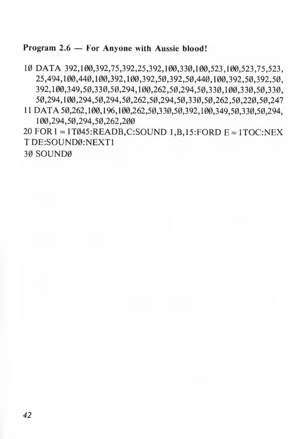
Program 2.6 — For Anyone with Aussie blood!
10 DATA 392,100,392,75,392,25,392,100,330,100,523,100,523,75,523,
25,494,100,440,100,392,100,392,50,392,50,440,100,392,50,392,50,
392,100,349,50,330,50,294,100,262,50,294,50,330,100,330,50,330,
50,294,100,294,50,294,50,262,50,294,50,330,50,262,50,220,50,247
11 DATA 50,262,100,196,100,262,50,330,50,392,100,349,50,330,50,294,
100,294,50,294,50,262,200
20 FOR 1 = 1T045:READB,C:SOUND
1 ,B,15:FORD E = 1T0C:NEX
T DE:SOUND0:NEXT1
30 SOUND0
42
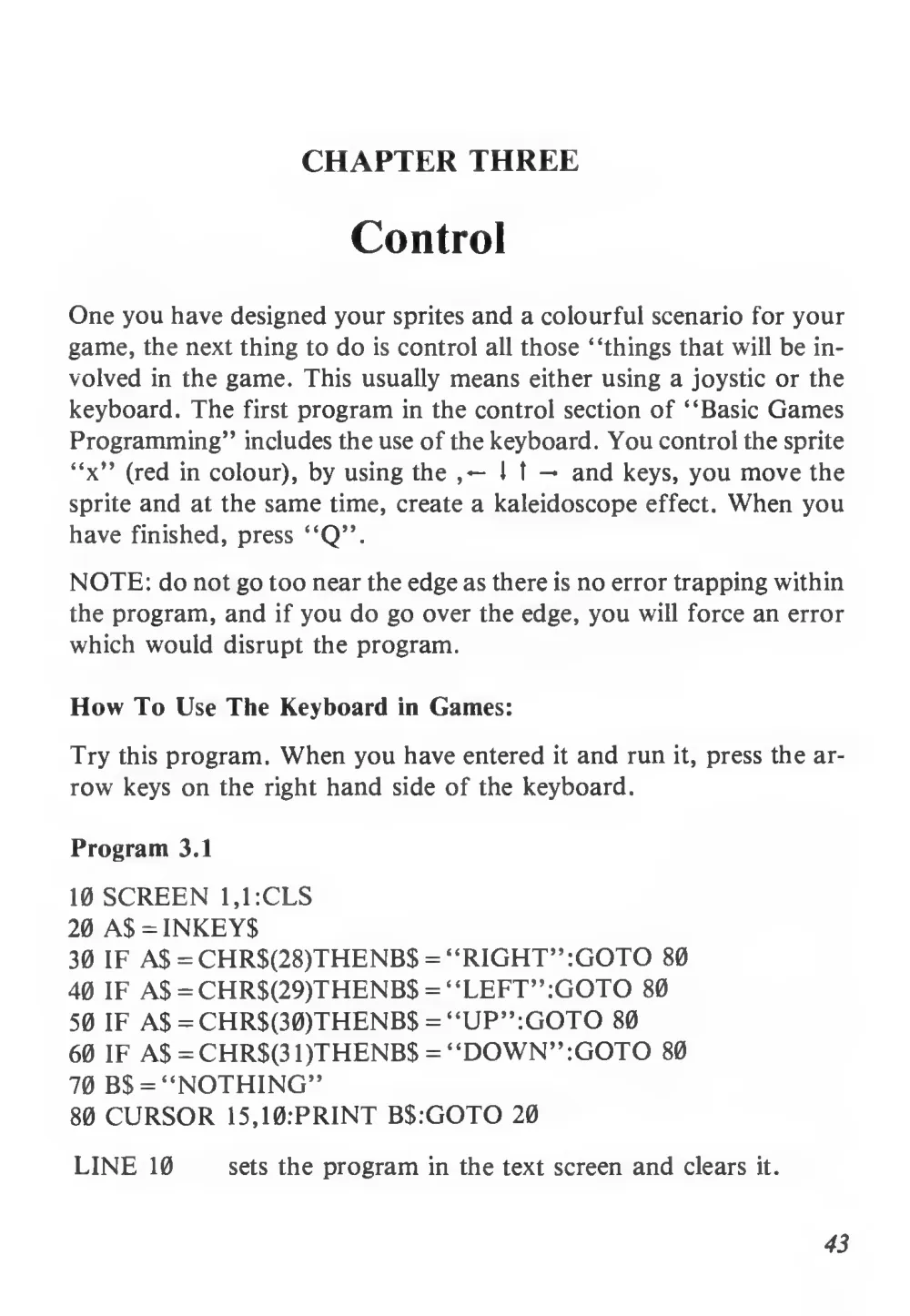
CHAPTER THREE
Control
One you have designed your sprites and a colourful scenario for your
game, the next thing to do
is control all those “things that will be in-
volved in the game. This usually means either using a joystic or the
keyboard. The first program in the control section of “Basic Games
Programming” includes the use of the keyboard. You control the sprite
“x” (red in colour), by using the ,—
J
t — and keys, you move the
sprite and at the same time, create a kaleidoscope effect. When you
have finished, press “Q”.
NOTE: do not go too near the edge as there is no error trapping within
the program, and if you do go over the edge, you will force an error
which would disrupt the program.
How To Use The Keyboard in Games:
Try this program. When you have entered
it and run
it, press the ar-
row keys on the right hand side of the keyboard.
Program 3.1
10 SCREEN 1,1:CLS
20 A$ = INKEYS
30 IF AS = CHR$(28)THENB$ = “RIGHT”:GOTO 80
40 IF AS =CHR$(29)THENB$ = “LEFT”:GOTO 80
50 IF AS = CHR$(30)THENB$ = “UP”:GOTO 80
60 IF AS = CHR$(31)THENB$ = “DOWN”:GOTO 80
70 B$ = “NOTHING”
80 CURSOR 15,10:PRINT B$:GOTO 20
LINE 10
sets the program in the text screen and clears
it.
43
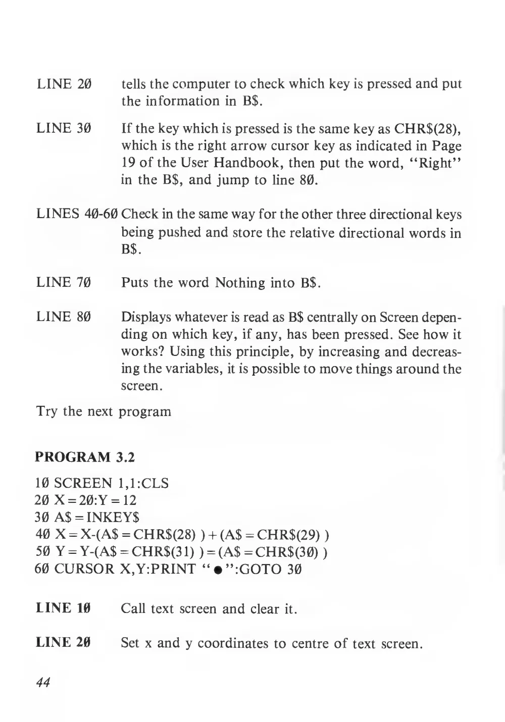
LINE 20
tells the computer to check which key is pressed and put
the information in B$.
LINE 30
If the key which is pressed is the same key as CHR$(28),
which is the right arrow cursor key as indicated in Page
19 of the User Handbook, then put the word, “Right”
in the B$, and jump to line 80.
LINES 40-60 Check in the same way for the other three directional keys
being pushed and store the relative directional words in
B$.
LINE 70
Puts the word Nothing into B$.
LINE 80
Displays whatever is read as B$ centrally on Screen depen-
ding on which key,
if any, has been pressed. See how
it
works? Using this principle, by increasing and decreas-
ing the variables,
it is possible to move things around the
screen.
Try the next program
PROGRAM 3.2
10 SCREEN 1,1:CLS
20 X = 20:Y = 12
30 A$ = INKEYS
40 X = X-(A$ = CHR$(28)
) + (AS = CHR$(29)
)
50 Y = Y-(A$ = CHR$(3 1)
) = (AS = CHR$(30)
)
60 CURSOR X,Y:PRINT “#”:GOTO 30
LINE 10
Call text screen and clear
it.
LINE 20
Set x and y coordinates to centre of text screen.
44
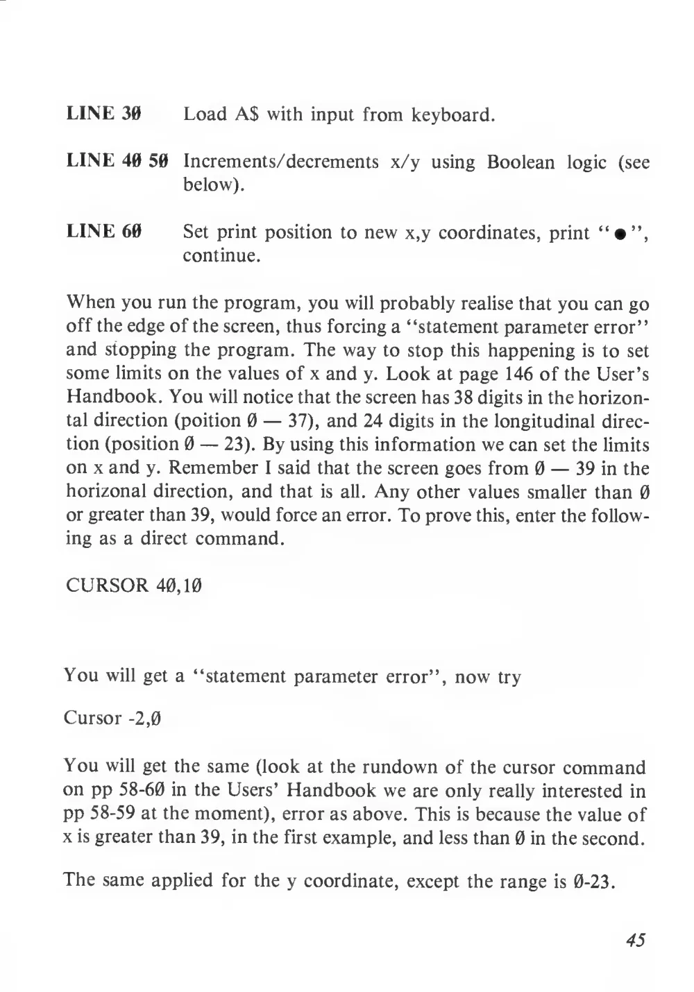
LINE 30
Load A$ with input from keyboard.
LINE 40 50
Increments/decrements x/y
using
Boolean
logic
(see
below).
LINE 60
Set print position to new x,y coordinates, print
continue.
When you run the program, you will probably realise that you can go
off the edge of the screen, thus forcing a “statement parameter error”
and stopping the program. The way to stop this happening
is to set
some limits on the values of x and y. Look at page 146 of the User’s
Handbook. You will notice that the screen has 38 digits in the horizon-
tal direction (poition 0 — 37), and 24 digits in the longitudinal direc-
tion (position 0 — 23). By using this information we can set the limits
on x and y. Remember
I said that the screen goes from 0 — 39 in the
horizonal direction, and that
is
all. Any other values smaller than 0
or greater than 39, would force an error. To prove this, enter the follow-
ing as a direct command.
CURSOR 40,10
You will get a “statement parameter error”, now try
Cursor -2,0
You will get the same (look at the rundown of the cursor command
on pp 58-60 in the Users’ Handbook we are only really interested in
pp 58-59 at the moment), error as above. This is because the value of
x is greater than 39, in the first example, and less than 0 in the second.
The same applied for the y coordinate, except the range
is 0-23.
45
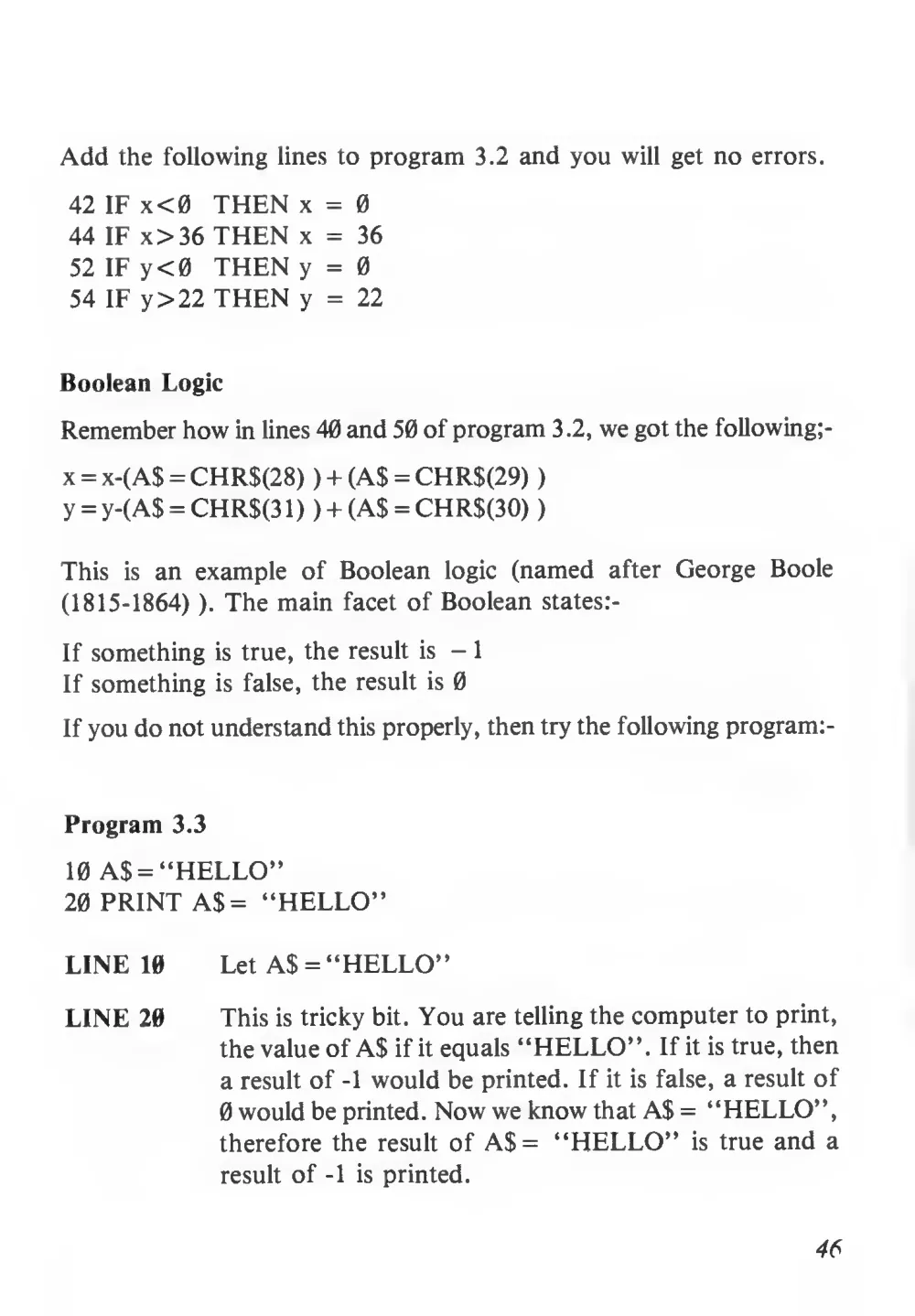
Add the following lines to program 3.2 and you will get no errors.
42 IF x < 0 THEN x =
0
44 IF x>36 THEN x = 36
52 IF y<0 THEN y = 0
54 IF y >22 THEN y = 22
Boolean Logic
Remember how in lines 40 and 50 of program 3.2, we got the following;-
x = x-(A$ = CHR$(28)
) + (A$ = CHR$(29)
)
y = y-(A$ = CHR$(3 1 )
) + (AS = CHR$(30)
)
This
is an example
of Boolean
logic (named
after George Boole
(1815-1864)
). The main facet of Boolean states:-
If something
is true, the result
is -
1
If something
is false, the result
is 0
If you do not understand this properly, then try the following program:-
Program 3.3
10 A$ = “HELLO”
20 PRINT AS = “HELLO”
LINE 10
Let AS = “HELLO”
LINE 20
This is tricky bit. You are telling the computer to print,
the value of AS if it equals “HELLO”. If it is true, then
a result of -1 would be printed. If it is false, a result of
0 would be printed. Now we know that AS = “HELLO”,
therefore the result of A$ = “HELLO”
is true and a
result of -1
is printed.
46
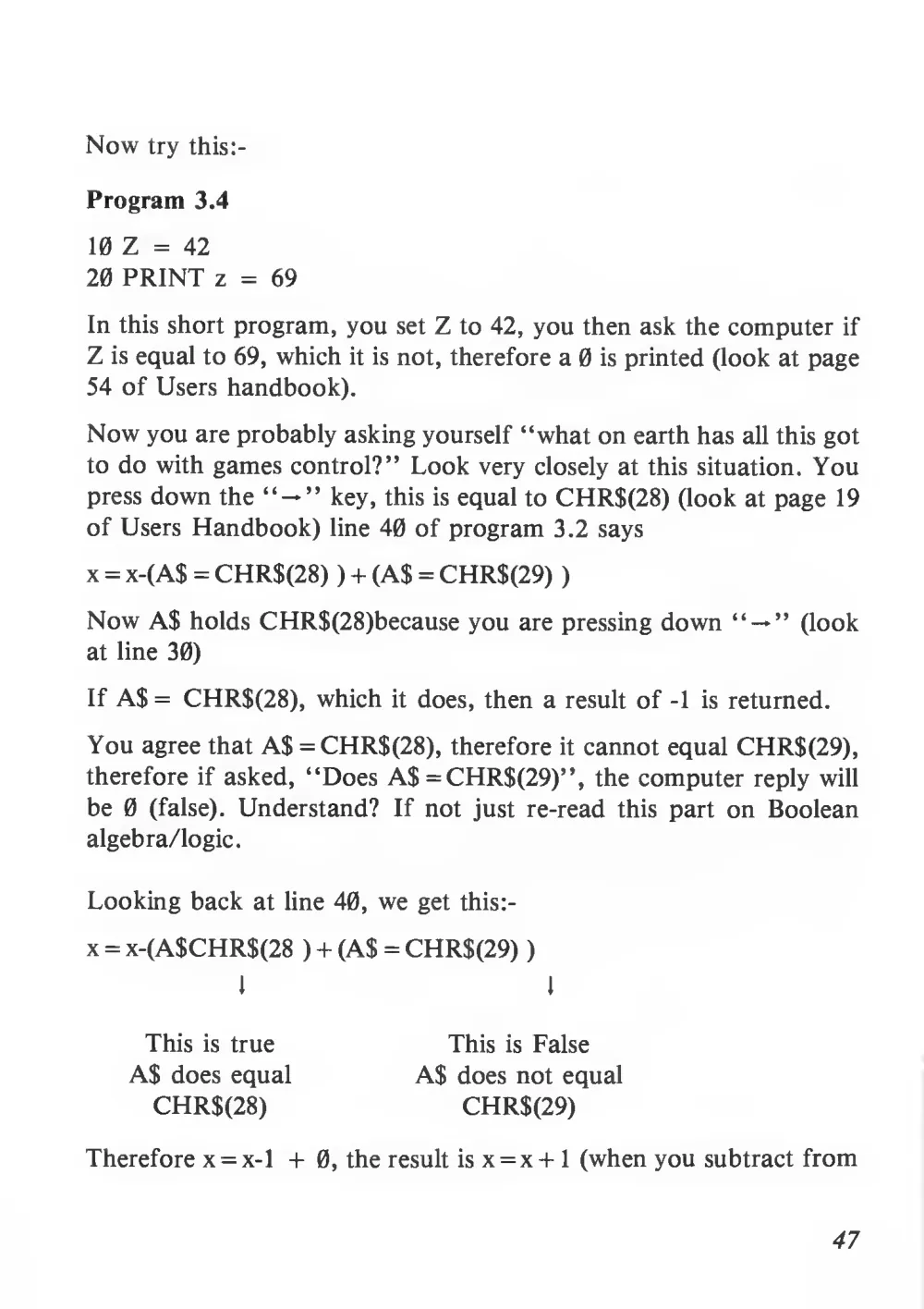
Now try this:-
Program 3.4
10 Z = 42
20 PRINT z =
69
In this short program, you set Z to 42, you then ask the computer if
Z is equal to 69, which
it is not, therefore a 0
is printed (look at page
54 of Users handbook).
Now you are probably asking yourself “what on earth has all this got
to do with games control?” Look very closely at this situation. You
press down the “ — ” key, this
is equal to CHR$(28) (look at page 19
of Users Handbook) line 40 of program 3.2 says
x = x-(A$ = CHR$(28)
) + (A$ = CHR$(29)
Now A$ holds CHR$(28)because you are pressing down “ — ” (look
at line 30)
If A$= CHR$(28), which
it does, then a result of -1
is returned.
You agree that A$ = CHR$(28), therefore
it cannot equal CHR$(29),
therefore
if asked, “Does A$ = CHR$(29)”, the computer reply will
be 0
(false). Understand?
If not just re-read
this part on Boolean
algebra/logic.
Looking back at line 40, we get this:-
x = x-(A$CHR$(28
) + (A$ = CHR$(29)
)
This
is true
A$ does equal
CHR$(28)
This
is False
A$ does not equal
CHR$(29)
Therefore x = x-l +
0, the result
is x = x+ 1 (when you subtract from
47
a negative number (in this case -1) it is the same as adding the positive
number e.g.
2- -4
is equal to 2 + 4 =
6.
So if you are holding down the
key, x will be added to by
1, the
result of which
is to move the cursor position, to the right.
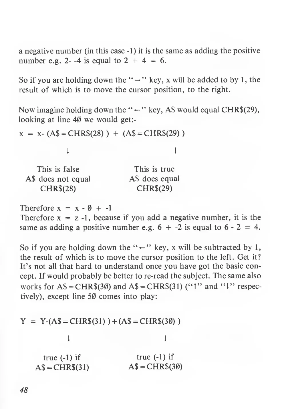
Now imagine holding down the
” key, A$ would equal CHR$(29),
looking at line 40 we would get:-
x =
x- (A$ = CHR$(28)
) + (A$ =CHR$(29)
)
This
is true
A$ does equal
CHR$(29)
This
is false
A$ does not equal
CHR$(28)
Therefore x = x
- 0 +
-1
Therefore x =
z -1, because
if you add a negative number,
it
is the
same as adding a positive number e.g. 6 +
-2
is equal to 6
- 2 =
4.
So
if you are holding down the “ — ” key, x will be subtracted by
1,
the result of which
is to move the cursor position to the
left. Get it?
It’s not all that hard to understand once you have got the basic con-
cept. If would probably be better to re-read the subject. The same also
works for A$ = CHR$(30) and A$ = CHR$(31) (“1” and “1” respec-
tively), except line 50 comes into play:
Y = Y-(A$ = CHR$(31)
) + (A$ = CHR$(30)
)
true (-1)
if
A$ = CHR$(31)
true (-1)
if
A$ = CHR$(30)
48
Problem 3.1
What would happen if A$ does not equal CHR$(28) or CHR$(29) or
CHR$(30) or CHR$(31)?
ie. you don’t press “ —
“t”, “l”?
If you understand all the above on control, you know 99% of control
using the keyboard!
Use of Joysticks
For true control, you need a joystick. The S.C. 3000 has the provision
for two joysticks. These are located on the
left of the computer.
The second part of the control section of “Basic Games Programm-
ing” involves the use of a joystick placed in port
1.
By directing the joystick in any direction, you can get the sprite “x”
to move and leave a trail behind
it. If you press the left fire button,
you can erase dots by moving over the dots, and by pressing the right
fire button, you can paint an area.
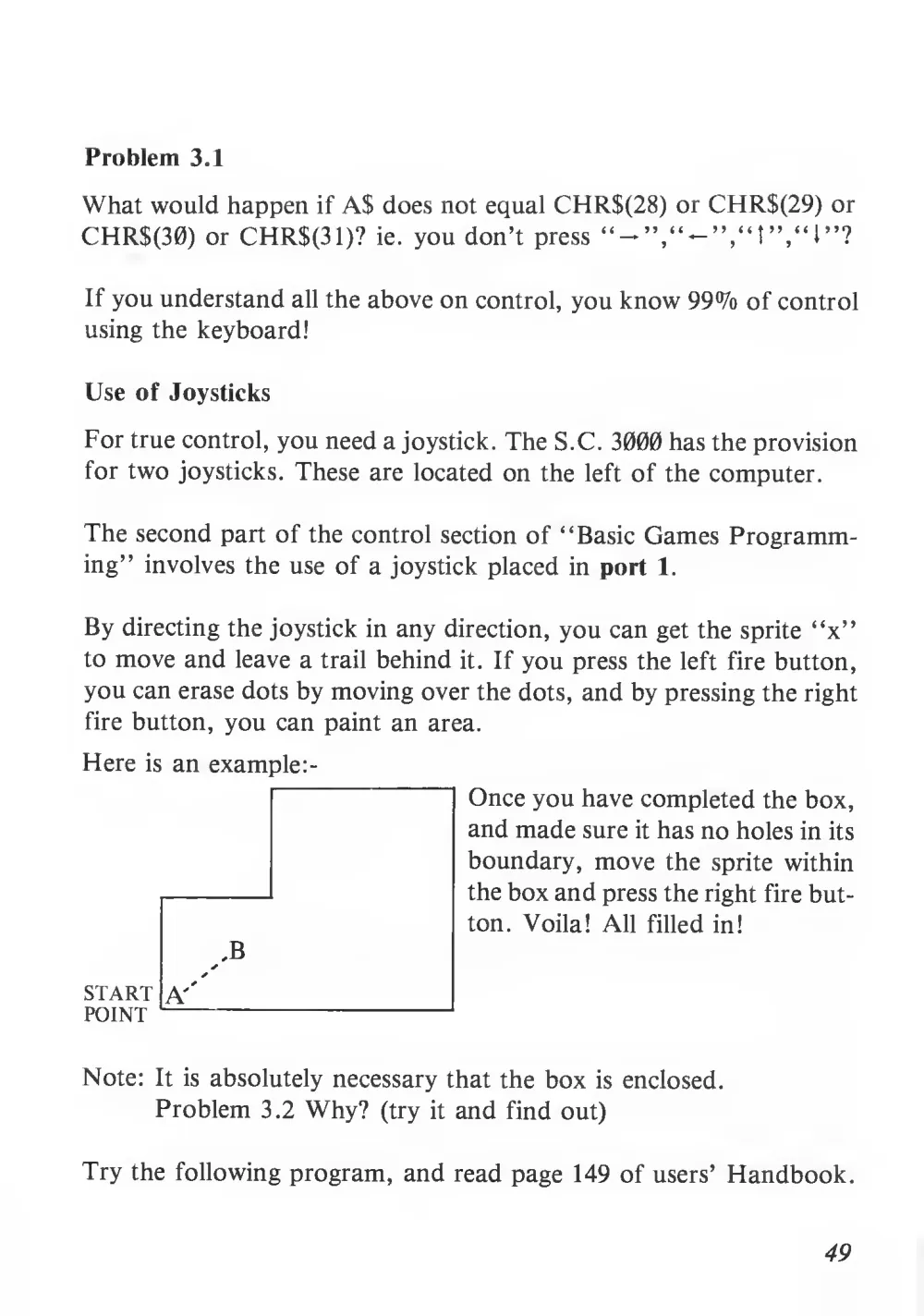
Here
is an example
,B
START A''
POINT
Once you have completed the box,
and made sure it has no holes in its
boundary, move the sprite within
the box and press the right fire but-
ton. Voila! All
filled in!
Note:
It
is absolutely necessary that the box
is enclosed.
Problem 3.2 Why?
(try
it and find out)
Try the following program, and read page 149 of users’ Handbook.
49
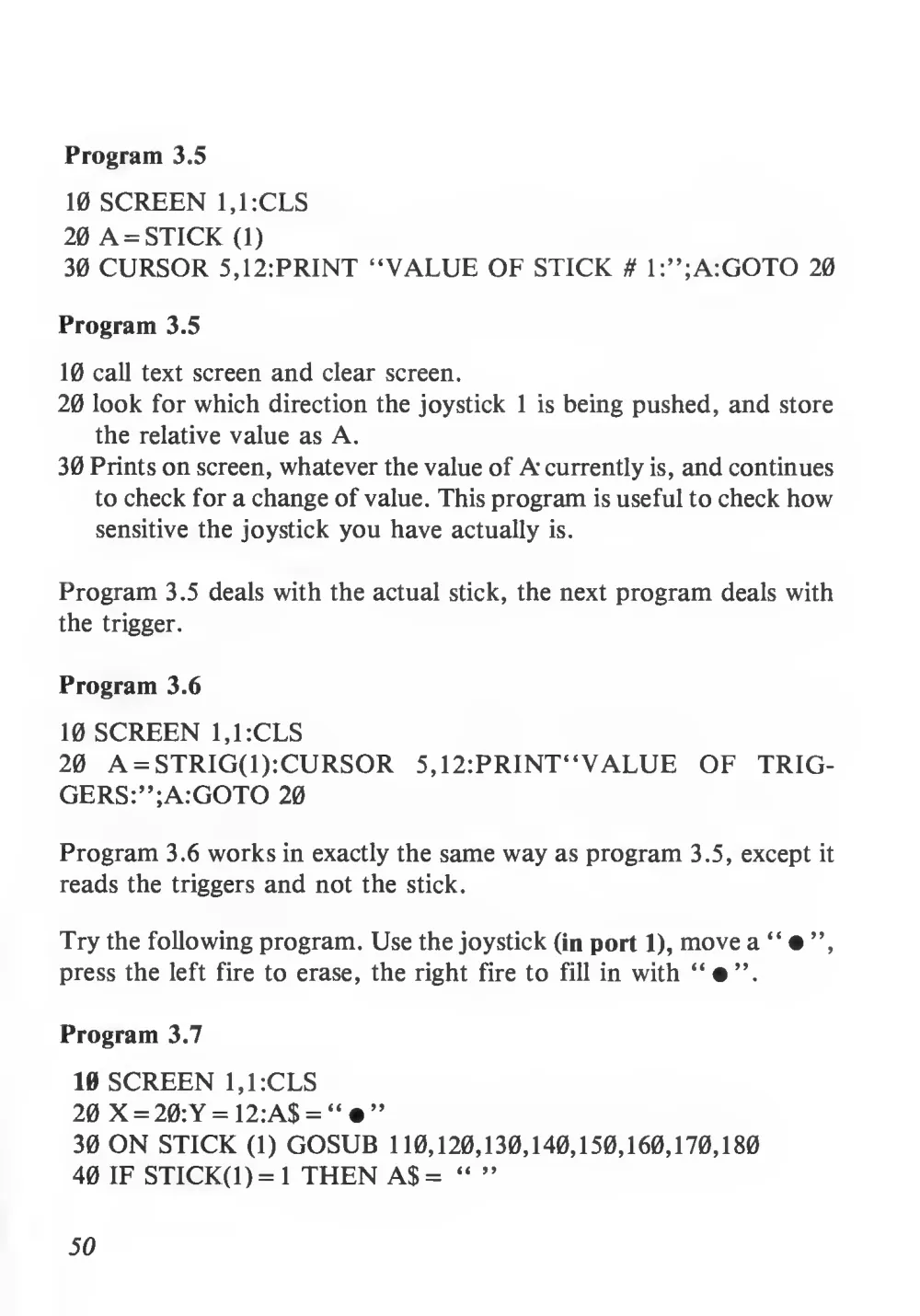
Program 3.5
10 SCREEN 1,1:CLS
20 A = STICK (1)
30 CURSOR 5,12:PRINT “VALUE OF STICK # l:”;A:GOTO 20
Program 3.5
10 call text screen and clear screen.
20 look for which direction the joystick
1
is being pushed, and store
the relative value as A.
30 Prints on screen, whatever the value of A currently is, and continues
to check for a change of value. This program is useful to check how
sensitive the joystick you have actually
is.
Program 3.5 deals with the actual stick, the next program deals with
the trigger.
Program 3.6
10 SCREEN 1,1:CLS
20 A = STRIG(l):CURSOR
5,12:PRINT“VALUE OF
TRIG-
GERS:”;A:GOTO 20
Program 3.6 works in exactly the same way as program 3.5, except
it
reads the triggers and not the stick.
Try the following program. Use the joystick (in port 1), move a “ • ”,
press the left fire to erase, the right
fire to
fill in with “ • ”.
Program 3.7
10 SCREEN 1,1:CLS
20 X = 20:Y = 12:A$ = “ • ”
30 ON STICK (1) GOSUB 110,120,130,140,150,160,170,180
40 IF STICK(l) = 1 THEN A$= “ ”
50
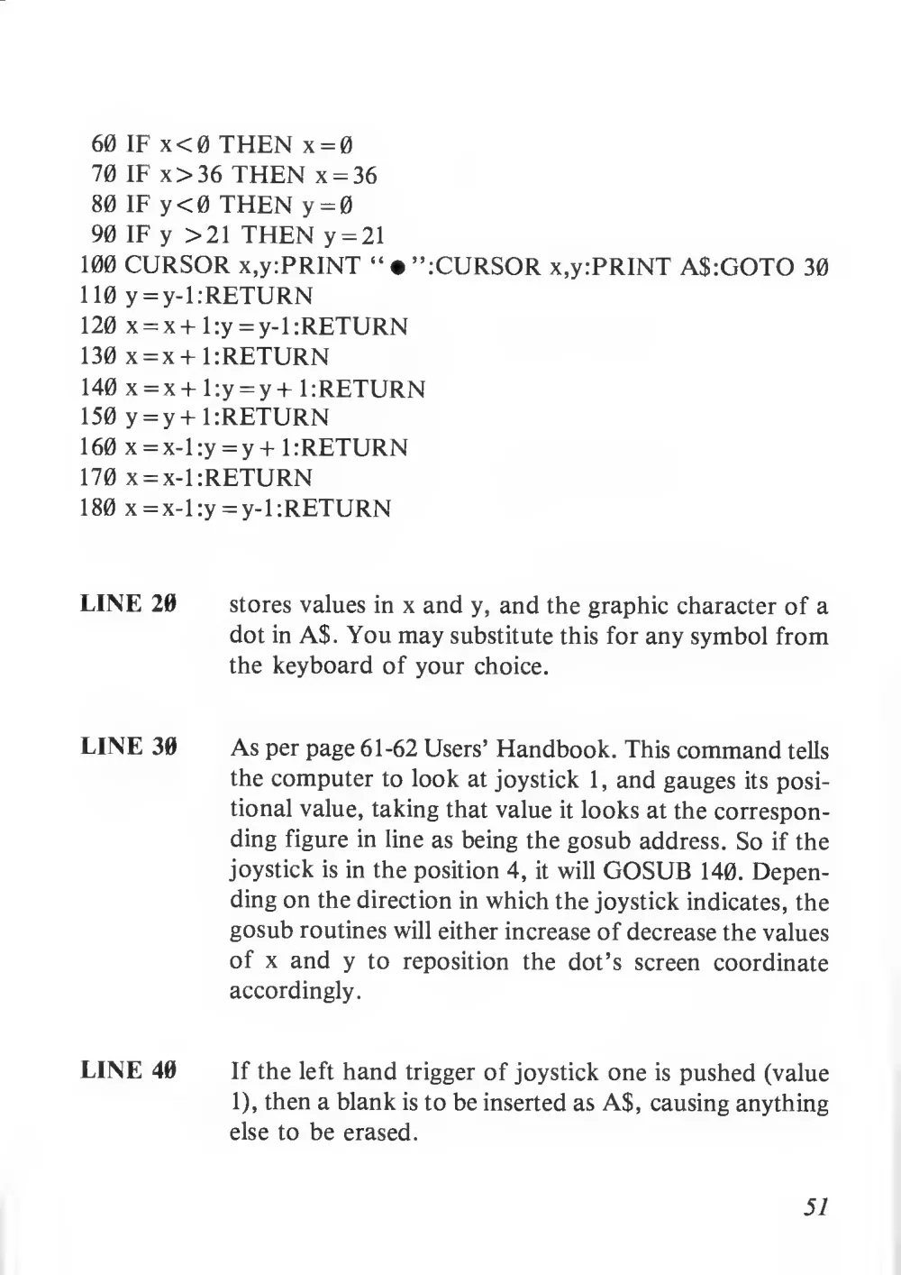
60 IF x < 0 THEN x = 0
70 IF x> 36 THEN x = 36
80 IF y<0 THEN y = 0
90 IF y >21 THEN y = 21
100 CURSOR x,y:PRINT “ • ”:CURSOR x,y:PRINT A$:GOTO 30
110 y = y-l:RETURN
120 x = x+l:y = y-l .-RETURN
130 x = x+ URETURN
140 x = x+ l:y = y+ URETURN
150 y = y+ URETURN
160 x = x-l:y = y+ URETURN
170 x = x-l:RETURN
1 80 x = x-Uy = y-1 rRETURN
LINE 20
stores values in x and y, and the graphic character of a
dot in A$. You may substitute this for any symbol from
the keyboard of your choice.
LINE 30
As per page 61-62 Users’ Handbook. This command tells
the computer to look at joystick
1
, and gauges its posi-
tional value, taking that value it looks at the correspon-
ding figure in line as being the gosub address. So if the
joystick is in the position 4,
it will GOSUB 140. Depen-
ding on the direction in which the joystick indicates, the
gosub routines will either increase of decrease the values
of x and y
to
reposition
the
dot’s
screen coordinate
accordingly.
LINE 40
If the left hand trigger of joystick one is pushed (value
1), then a blank is to be inserted as A$, causing anything
else to be erased.
51
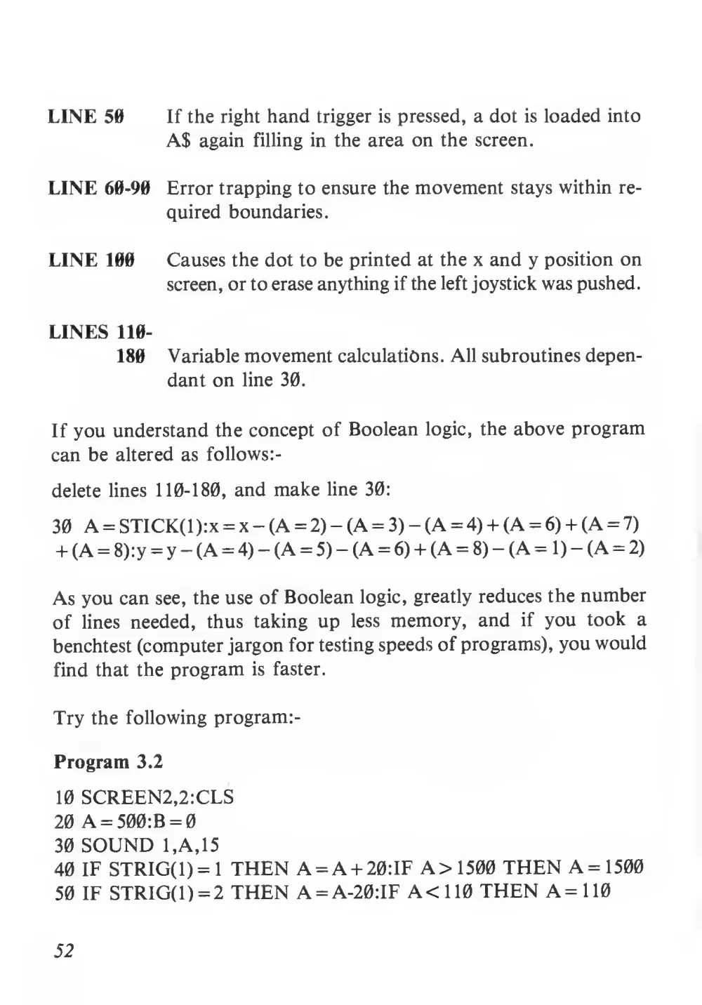
LINE 50
If the right hand trigger
is pressed, a dot
is loaded into
AS again
filling in the area on the screen.
LINE 60-90
Error trapping to ensure the movement stays within re-
quired boundaries.
LINE 100
Causes the dot to be printed at the x and y position on
screen, or to erase anything if the left joystick was pushed.
LINES 110-
180
Variable movement calculations. All subroutines depen-
dant on line 30.
If you understand the concept of Boolean logic, the above program
can be altered as follows:-
delete lines 110-180, and make line 30:
30 A = STICK(l):x = x — (A = 2) — (A = 3) — (A = 4) + (A = 6) + (A = 7)
+ (A = 8):y = y — (A = 4) — (A = 5) — (A = 6) + (A = 8) - (A = 1) — (A = 2)
As you can see, the use of Boolean logic, greatly reduces the number
of
lines
needed,
thus
taking up
less memory,
and
if you took a
benchtest (computer jargon for testing speeds of programs), you would
find that the program
is faster.
Try the following program:-
Program 3.2
10 SCREEN2,2:CLS
20 A = 500:B = 0
30 SOUND 1,A,15
40 IF STRIG(1)= 1 THEN A = A + 20:IF A> 1500 THEN A=1500
50 IF STRIG(1) = 2 THEN A = A-20:IF A <110 THEN A=110
52
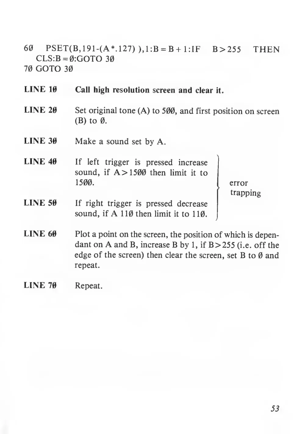
60
PSET(B, 191-(A*. 127) ),1:B = B+
1
: IF
B>255
THEN
CLS:B=0:GOTO 30
70 GOTO 30
LINE 10
Call high resolution screen and clear
it.
LINE 20
Set original tone (A) to 500, and first position on screen
(B) to 0.
LINE 30
Make a sound set by A.
LINE 40
If
left
trigger
is
pressed
increase
sound,
if A > 1500 then
limit
it
to
1500.
LINE 50
If
right
trigger
is pressed decrease
sound,
if A
1 10 then limit
it to
1 10.
LINE 60
Plot a point on the screen, the position of which is depen-
dant on A and B, increase B by
1
, if B > 255 (i.e. off the
edge of the screen) then clear the screen, set B to 0 and
repeat.
LINE 70
Repeat.
error
trapping
53
CHAPTER FOUR
Games Programming as an Art
Manipulating the Screen
This chapter will deal with manipulation of the text screen, the reason
for this is that the text screen is much easier to use than the high resolu-
tion screen, although
I am sure that with a bit of ingenuity, you will
be able to use the high -res screen efficiently.
Firstly, a bit of technological knowledge. The S.C. 3000 contains a very
special chip called a Video Display processor (VDP). This chip was
created by Texas Instruments and its serial number is TI TMM9929A
(bit of a mouthfull!) The information on both the text screen, and high
resolution screens is stored in this chip. This is called Video Random
Access Memory (VRAM).
Now we know where the screen is stored, so how do we access it? Im-
agine you have a friend
called Bert J. Smith. This is a bit of informa-
tion, okay? He lives at 100 Knot Close, Williamstown, Mars. This
is
the address, okay? So if you wanted to store this information you might
write:
Smith, Bert
J,;
100 Knot Close, Williamstown, Mars
Information
Address
In the VRAM, the way to access or store information is identical. The
only
difference
is
that
the
address
is from &H0000
to &H3FFF
(remember the &H means the numbers are hexidecimal), and the in-
formation is any number from &H00 to &HFF.
If you want to place
54
information in the video ram, you use the VPOKE command, which
literally means “shoving information into the VRAM”. The informa-
tion for the text screen is held between address &H3C00 and &H3FC0.
To try out the VPOKE command, do the following, clear the screen
(by using CLS).
VPOKE &H3C26,&H2A
You will get a
in the top of the screen. What you have done
is
shoved the information (&H2A, which is a
look at page 156 of
Users’ Manual), into address &EI3C26 (which
is indeed the top right
of the text screen). Okay, so now we have stored that information in
VRAM, how do we get it out again? Well we can see it!
It is that asterisk
in the top right! The proper way about it is by using the VPEEK com-
mand. Remember we put &H2A (which is 42 in decimal) into address
&EI3C26, so in theory,
if we VPEEK’ed &H3C26, we should get 42
in decimal)
into address &EI3C26,
so
in theory,
if we VPEEK’ed
&H3C26, we should get 42 decimal (or &H24). So now enter:
PRINT VPEEK &H3C26
And what do you get? 42!! Voila. Try other values of address and in-
formation, and refer to pp 143-148. We are interested mostly, in the
left hand side of page 143 of the Users’ Handbook and the top of page
144. The next small part is to explain the wierd diagram on page 148
of the User’s Handbook.
Video Ram Map
A memory map
is just a diagram showing what
all the different ad-
dresses do. The diagram on page 148
is a map of the memory in the
VDP.
Address Range
Description
&H0000 — &H17FF
Holds
data
for
contents
of
the
High
Resolution Screen.
55
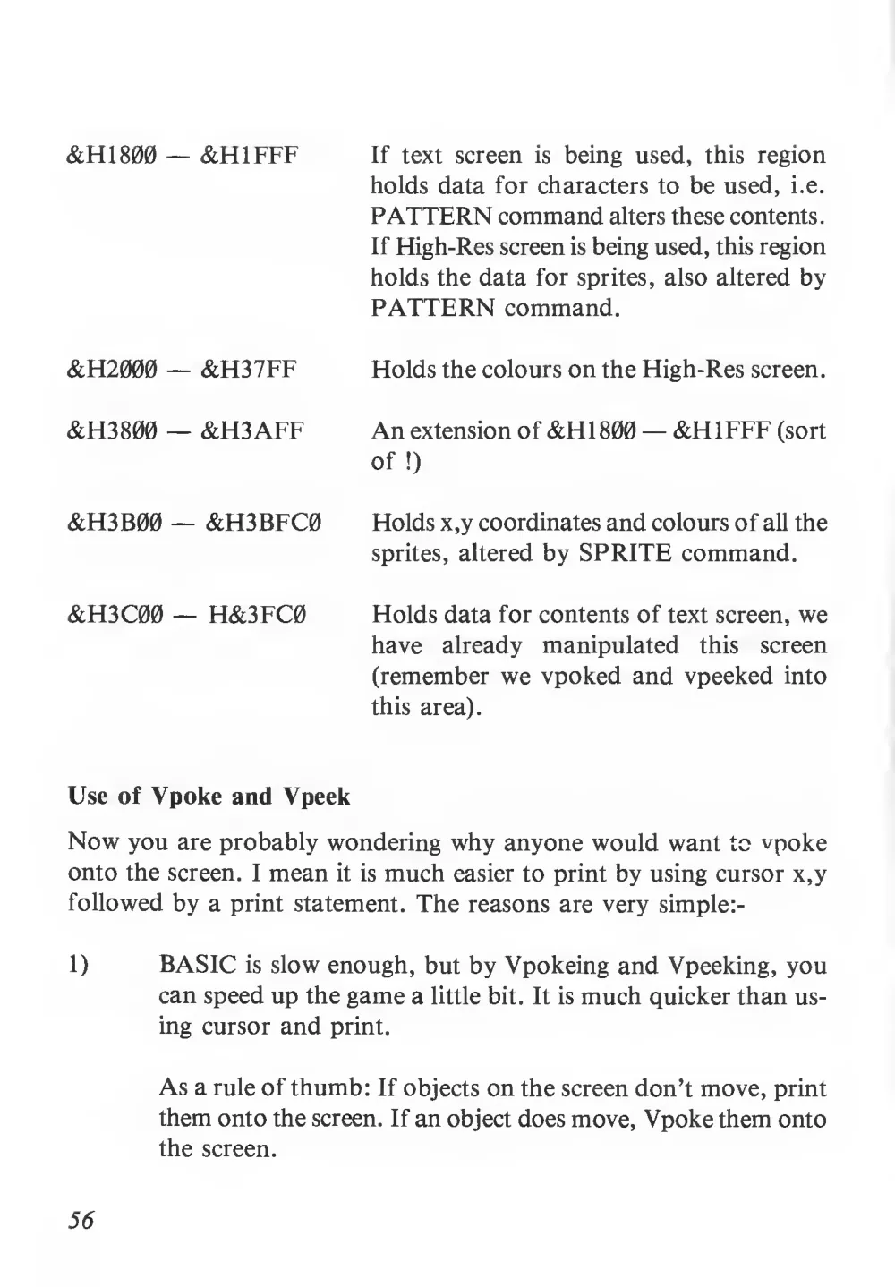
&H1800 — &H1FFF
If text screen
is being used,
this region
holds data for characters to be used,
i.e.
PATTERN command alters these contents.
If Fligh-Res screen is being used, this region
holds the data for sprites, also altered by
PATTERN command.
&H2000 — &H37FF
Holds the colours on the High-Res screen.
&H3800 — &H3AFF
An extension of &H1800 — &H1FFF (sort
of
!)
&H3B00 — &H3BFC0
Holds x,y coordinates and colours of all the
sprites, altered by SPRITE command.
&H3C00 — H&3FC0
Holds data for contents of text screen, we
have
already
manipulated
this
screen
(remember we vpoked and vpeeked into
this area).
Use of Vpoke and Vpeek
Now you are probably wondering why anyone would want to vpoke
onto the screen.
I mean
it is much easier to print by using cursor x,y
followed by a print statement. The reasons are very simple:-
1)
BASIC
is slow enough, but by Vpokeing and Vpeeking, you
can speed up the game a little bit.
It is much quicker than us-
ing cursor and print.
56
As a rule of thumb: If objects on the screen don’t move, print
them onto the screen. If an object does move, Vpoke them onto
the screen.
2)
Imagine in a game of Pacman *, the only way to stop the little
man from going through a wall,
is to look one square ahead.
If it is not a wall, then the man can continue in that direction.
If it is a wall he cannot get through. If you were Vpokeing the
man onto the screen, then you could Vpeek the next square
to see if
it
is a wall or not. On the other hand,
if you were
printing on the screen, there would be no simple way of look-
ing one space ahead, thus making games writing impossible!
Let’s face
it,
if you don’t know what
is surrounding your
man/ship/frog etc., how can you find out if you have eaten
a power pill, been muched by a ghost, hit a wall, whether the
bullet you shot has hit an alien or a base, whether your frog
has been eaten by a crocodile, been hit by a truck, or got home,
or whether Mario has been struck by a fire ball or picked up
a hammer, or whether your ship has run into a lander or mu-
tant, or picked up a humanoid? As I am sure you can see, the
ability to look around you is extremely important, and this can
only be done by Vpeek! (The above examples are taken from
Pacman*,
Space
Invader*,
Frogger*, Donkey Kong* and
Defender*.
If Vokeing and Vpeeking seems a little complex, then the next thing
to do
is to use x and y coordintes for your
little man (or woman or
frog, or ship etc.,) then convert this to an address, then Vpeek that
address. This can be done very simply by using the following formula.
(This
is for the text screen only).
Address (text screen) = Y*40 + x + &H3C00
Where x and y are the coordinates of your man etc., (This formula
is given on the top of page 144 of the users’ Handbook). An example
of this
is given in the game of “Maze Chase” in the “Basic Games
Programming” Program. It is probably best to play the game a couple
of times, before I describe how it works. If you have a joystick attach-
ed to port
1, then just use the stick to steer your man. If not, use the
* Registered Trade Marks
57
arrow keys. The baddie moves randomly (i.e. sometimes he may stay
where he is, other times he may move), but he always comes straight
for you!
Things to remember
“O” = CHR$ (235) = You
= CHR$ (236) = Home
= CHR$ (229) = Walls
“m” = CHR$ (253) = Baddie (CHR$ (253) is originally “
|” but this
is redefined)
“x” = CHR$ (228) = You eat these
RUN DOWN OF GAME — MAZE CHASE
Begin by breaking into the “Basic Games Programming Cassette”
(preferably once it is loaded in the computer, not with a hammer), by
pushing the break key, then give the command LIST 1690 — to show
the program. Control the scrolling action with the space bar.
LINE 1690
This line sets up the control of our characters movements
around
the
screen, and
prints a prompt
to
find
out
whether we will use keyboard control or joystick.
LINE 1700
Sets A$ as Inkey variable,
if key Y
is pushed, variable
J becomes 2 and the program jumps to joystick control
section from 1730 onward.
LINE 1710
If N is PUSHED J becomes
1 and Line 1730 will be ex-
ecuted as
it will be true and the program jumps straight
to Line 1940 to commence the game controlled by the
keyboard.
58
LINE 1720
Keeps the program scanning until a key
is pushed.
LINE 1940
Call text screen, clear screen.
LINE 1950
Set titles for screen.
LINE 1960
Redefine character 253 (see page 155 Users’ Handbook)
as a pattern (UDG) and set up on screen instructions.
LINE 1970
Define pattern for the “x”. Print instructions.
LINE 1980
Draws a small thick line representing a wall, sets variable
S to 0. S will become the variable holding the Score.
LINE 1990
At position one row across, 20 down display Score =
LINE 2000
Sets A as a slowly reducing value from 35 to 30 and print
O which
is representing you,
at location 35 down
17
across, a sound like a footprint is then made, before the
line goes back and changes the position of o one to the
left as A is reduced in value, each change is accompanied
by the footprint sound. A$
is then defined as O Five
spaces away from the symbol which will chase us i3, T = o
to 10 causes a brief delay in each movement.
LINE 2010
Produces the same action as Line 2000, using the two
characters in A$, making the appearance of a chase. The
delay
is shorter, therefore the movement
is quicker.
LINE 2020
A$ appears to leave crosses behind as it moves across the
screen, by printing x in the vacated cursor positions.
59
LINE 2030
LINE 2040
LINE 2060
LINE 2070
LINE 2080
LINE 2090
The trail of x’s
is increased by adding to the length of
A$, seven times as the value of a decreases.
ONow appears on screen and moves over the trail of x’s,
the
sound
changes
as
we
eat
the
dots
which
are
automatically erased. The value of S increases by
1 each
time we move and
is printed out in the location next to
the word score on Screen. D stands for difficulty level,
and sets the number of blocks to be set out in the maze,
Score
is reset to 0.
Awaits a key to be pushed to continue.
Creates two different small sound scales played together,
one increasing in tone, the other decreasing.
Builds a boundary wall
all around the Screen with one
solid block printed across the top, 17 rows printed with
one block at the beginning of the line and one at the end.
ie. Print “
”
and one solid line printed at the bottom.
(Refer
Pg
134
Users’
Manual)
this
lines
sets
a
mathematical equation to randomly position the walls in-
side the playing area. We are defining this function as
Q. The A in brackets in this instance, is merely a dummy
argument and has no effect on the outcome. Once again
the calculations within brackets must be carried out first.
By referring to page 143 (Users’ Manual), you will see
&H3C00
is the location of the top
left hand corner of
the text screen, the calculation will add to that hex ad-
dress value, a random number between 0 and
1 multiplied
60
LINE 2100
LINE 2110
LINE 2120
by &H2D0. This hex address corresponds to the size of
the playing area, which
is the full width we set for the
border (1 to 17) so 40 x
18 = 720, which is 2D0 in Hex.
The reason we must add 2 at' the end of the calculation
is to stop blocks appearing outside the boundary. Because
the boundary was PRINTED on Screen as characters, and
because we can only display 38 characters across a line,
the balance must be allowed for. Therefore this calcula-
tion each time
it
is carried out, will produce a different
Hex Screen address, which will position a wall on the
playing area.
D sets the difficulty, it was previously 50, now it becomes
100, so 100 walls will be drawn to commence the game,
variable z, counts from 0 to whatever the difficulty level
is.
Variable x is loaded with the calculation stored in Func-
tion Q (the random address). VPEEK tells the computer
to have a look to check whether it is less than or greater
than 32. This refers to character 32 (Page 15A) which is
an empty space.
If not, then the space must be empty
and the program continues if there is anything there, the
computer goes back to the start of the line and chooses
another random location, as the NEXT command has not
yet been encountered, z will still be 0 and we will still have
100 walls to place.
VPOKE
puts
into
the screen
location held
in
x,
the
character numbered 229 (page 155) which is a wall. NEXT
send the computer back to For Z, which becomes
1 and
another location
is chosen on line 2110.
61
LINE 2120
LINE 2150
LINE 2160
LINE 2170
LINE 2190
LINE 2200
LINE 2220
When all z’s are used up, the program continues and z
becomes 0 or dummy argument, one more random loca-
tion is chosen, which providing it is empty, will on Line
2140, have character 236 representing “HOME” in the
game, positioned on Screen.
x becomes a random value between
1 and 35 Y a number
between
1 and 18. Representing coordinates within the
playing area, P
is then established as a Hex address us-
ing these random values. The coordinates are converted
to Hex using the standard calculation shown on Page 144
of Users’ Manual, the two is added to again put it inside
the playing area. P
is checked to ensure
it
is empty i.e.
VPEEK (P + 2).
Our character is then printed out at the chosen x y coor-
dinate. X and Y are then rounded to whole numbers.
2180 — Prints out the baddy shape at a different ran-
dom
screen
location (remember
this shape has been
redefined).
D1
is loaded with a whole number = the difficulty level,
divided by 50,-1, this will give us level 0,1,2, and so on
as the game progresses. This is then printed on screen for
information next to the current score, with
10 spaces
between.
Positions the instructions showing who is who at the bot-
tom of the screen.
Checks keyboard and joysticks for the command to start
the game by jumping to Line 1150.
62
LINE 2250
LINE 2260
LINE 2270
LINE 2280
LINE 2290
LINE 2300
LINE 2310
LINE 2320
Plays a chord to signal the start of the game and prints
a blank line to erase the “Push any Key” print.
The current Score and difficulty level are displayed.
To give our character a reasonable chance of survival,
the baddy is given only a 60-40 chance of moving. This
random choice will skip the baddy’s movement routine
if a number less than
.4
is selected, slowing him down
sometimes.
This works out using Boolean logic, which direction the
baddie has to move to catch up with us. Firstly, a “x”
is placed on the location of the baddy which is left as a
trail (remember z,w, are the baddies coordinates, and “I”
has
been
redefined
as an
x),
then
the
coordinate x
(remembering x, y, positions our character), is compared
to the z coordinate of the baddie.
If
it
is true that x
is
greater than y, the result is -1, causing the y coordinate
to increase, causing the movement of the baddie to follow
and home in our characters position.
Performs the same calculation to track our y coordinate
compared to the baddies equivalent coordinate W.
Checks to see whether we have been caught,
i.e. x and
z and y and w are the same. The death tune is played and
the program jumps to the final routine. If not, continue.
The new positions of us and the baddie are displayed.
Remember Lines 1700 and 1710, where the value of J was
63
LINE 2330
LINE 2340
LINE 2350
LINE 2360
LINE 2370-
2380
LINES 2390
2420
established? If it
is 2, then control
is by joystijck,
if
it
is
1, then
it
is keyboard. So at line 2360, the keyboard
direction program
is executed, at line 2460 the joystick
direction program.
When we have had our move, go back, alter the score
if we have picked up a point, and give the baddie a chance
to chase.
Prints the death line sequence, the final score S and screen
prompt to press any key.
Jumps to the inkey routine on Line 1060 to wait for a
key to be pushed, then once it is, recommences the game
from Lime 1940.
This is the keyboard movement subroutine, which looks
for a direction key being pushed to alter the value of x
and y. If no key is being pushed, the program immediately
returns and the baddie
is allowed to move.
The Boolean logic equations for movement.
Should a key have been pressed causing the value of x
and y to increase, these will have so far only have been
stored in XI and Yl, before we can put ourselves in the
new position on screen, we must check whether there is
already a wall there or a power cross, or our home. So
our new values of XI and Y 1 are converted to a hex screen
address as P two is added again and that location is peek
ed.
If there
is a wall there, the program returns to the
64
baddies turn without x and y actually being added to. If
not, the current x, y position has a blank printed to erase
our current position, the new value of XI and Y1 are
transferred
into
x, and
y,
and we
reappear
at
that
location.
LINE 2430-
2440
P
is then checked again to see if our home or a power
cross was stored in that location, altering our score or
sending us to the victory routine.
LINE 2450
Returns us to the baddies turn.
LINE 2460-
2480
Uses Boolean logic to check the joystick ports to deter-
mine direction.
LINE 2490
Jumps to the Peek routine to check direction Score and
home.
LINE 2500-
2510
The victory tune, and congrats print.
LINE 2520
Hit a key to go on.
LINE 2530
Jump to Inkey loop, add 20 to score, go back to restart
game and increase difficulty level.
65
Address:
Glossary
An area in memory. Data is stored in an address.
Binary:
A system of counting in “1” and “0”, used by
all
computers.
The
“l”s
and
“0”s
are
represented
in the computer by
electrical im-
pulses, either on or off.
Bit:
Binary digit, each bit represents a “1” or a “0”.
It
is the smallest unit of memory.
Boolean Logic/
Algebra:
A concept invented by E. Boole in the 19th cen-
tury. The concept states if something is true, let
the
result be
-1,
if
false,
let the
result be
0.
Boolean logic
is generally fast, and
is good for
game use.
Bug:
An error in a program.
Byte:
Eight bits, or two nibbles, can take a value of
&H00-&HFF (0-255).
Decimal:
A system of counting. Used
in everyday
life,
digits used are 0,1
9.
Error Trapping:
A method of limiting numbers or variables, so
as to detect an error, and rectify it. If an error
were to occurr, it would stop the program from
running, so if the error is detected and rectified,
the program will continue to function (read pp
162-165 of Users’ Handbook
for a
list of
all
possible errors).
66
Graphic Screen:
Called
up
by
using
SCREEN
2,2
(or
SHIFT/break pressed together), made up of 256
dots by 192 dots (0-255, 0-191).
Hex, Hexadecimal:
A system of counting to base
16,
digits used:
“0”
“9”, “A”
“F”. Used in many
applications in programming.
High Resolution
Screen:
See Graphic Screen.
Machine Code:
The
binary
language
that
the
computer
understands
directly. The BASIC language
is
converted into machinecode which the computer
then executes. In the case of the SC 3000, the
machine code used
is Z-80 machine code.
Map:
As a road map shows house addresses, a memory
map shows memory addresses, an example of a
memory map is given on page 148 of the Users’
Handbook.
Nibble:
4 Bits. Can take a value of &H00-&H0F (0-15).
Parameter:
The values which a command can take, e.g. the
PATTERN command has two parameters, the
first of which
is a character no. or sprite no.
(ranging from 0-255 or 0-31 respectively), the se-
cond
is 8 hexadecimal numbers.
RAM:
Random Access Memory. Any memory
into
which you can “read” (PEEK) data or “write”
(POKE) data from/to. See VRAM.
67
ROM:
Read Only Memory. Any memory in which in-
formation or instructions have been permanently
fixed. Usually contains the BASIC language and
other reference information.
Sprite:
A group of 8 x
8 dots, having
1 of 16 colours
and a set of coordinates. They are moved
in-
dependantly of the background and can only ap-
pear on the High-Res Screen.
Text Screen:
When computer is switched on, the text screen
is on.
It can be called using SCREEN
1,1 and
is made up of 40 characters x 24 characters.
UDG
Similar to a sprite except
is made up of 6 x
8
dots, and cannot be moved independantly of
background.
68